<span style='color:red'>PRI</span> Certification, the #2 Certification Body in China, Launches IATF 16949 Services to Support Growing Automotive Industry
  PRI Certification Expands by Adding IATF 16949 Certification Services in China and Enhances Position as One of the Top Two Chinese CBs with 18% Market Share  PRI Certification proudly announces the official launch of IATF 16949 certification services in China. The expansion through PRI China’s Beijing office allows the organization to offer IATF 16949 services directly to the Chinese marketplace. In addition to this stronger presence in China, PRI Certification also holds the #2 market share in the United States. This dual-market leadership underscores PRI’s global credibility and trusted reputation across two of the world’s most significant manufacturing regions.  This strategic move solidifies PRI Certification’s commitment to delivering high-quality, industry-specific certification solutions throughout Asia. While the Beijing office will serve as the local hub for client engagement and auditing, all technical and certification decisions will continue to be supported through PRI’s team in Warrendale, Pennsylvania, USA—ensuring global consistency, technical rigor, and impartial oversight.  Over a Decade of Experience in Asia  PRI Certification has been delivering IATF 16949 certification in Japan for over 10 years, earning a strong reputation for excellence and reliability in the region. Expanding into China is a natural progression that aligns with growing demand in the Asian automotive market.  Expert Auditors with Deep Automotive Knowledge  PRI’s auditors bring unmatched technical expertise and practical insight to each audit. This ensures clients receive not just compliance evaluations but also process improvements that contribute to lasting business value.  Tailored Audits Across 30+ Industries  PRI Certification has successfully delivered certification services across more than 30 industries worldwide. The organization’s approach to auditing is tailored to the specific needs of the automotive sector, making PRI a trusted partner for companies pursuing or maintaining IATF 16949 Certification.  Continuing a Legacy of Quality in China  PRI has been providing certification services in China since 2010, helping organizations achieve international quality benchmarks across a wide range of sectors. The introduction of IATF 16949 services marks a significant milestone, strengthening PRI’s ongoing commitment to the region’s automotive manufacturing excellence.
Key word:
Release time:2025-08-05 14:46 reading:533 Continue reading>>
BIWIN Wins
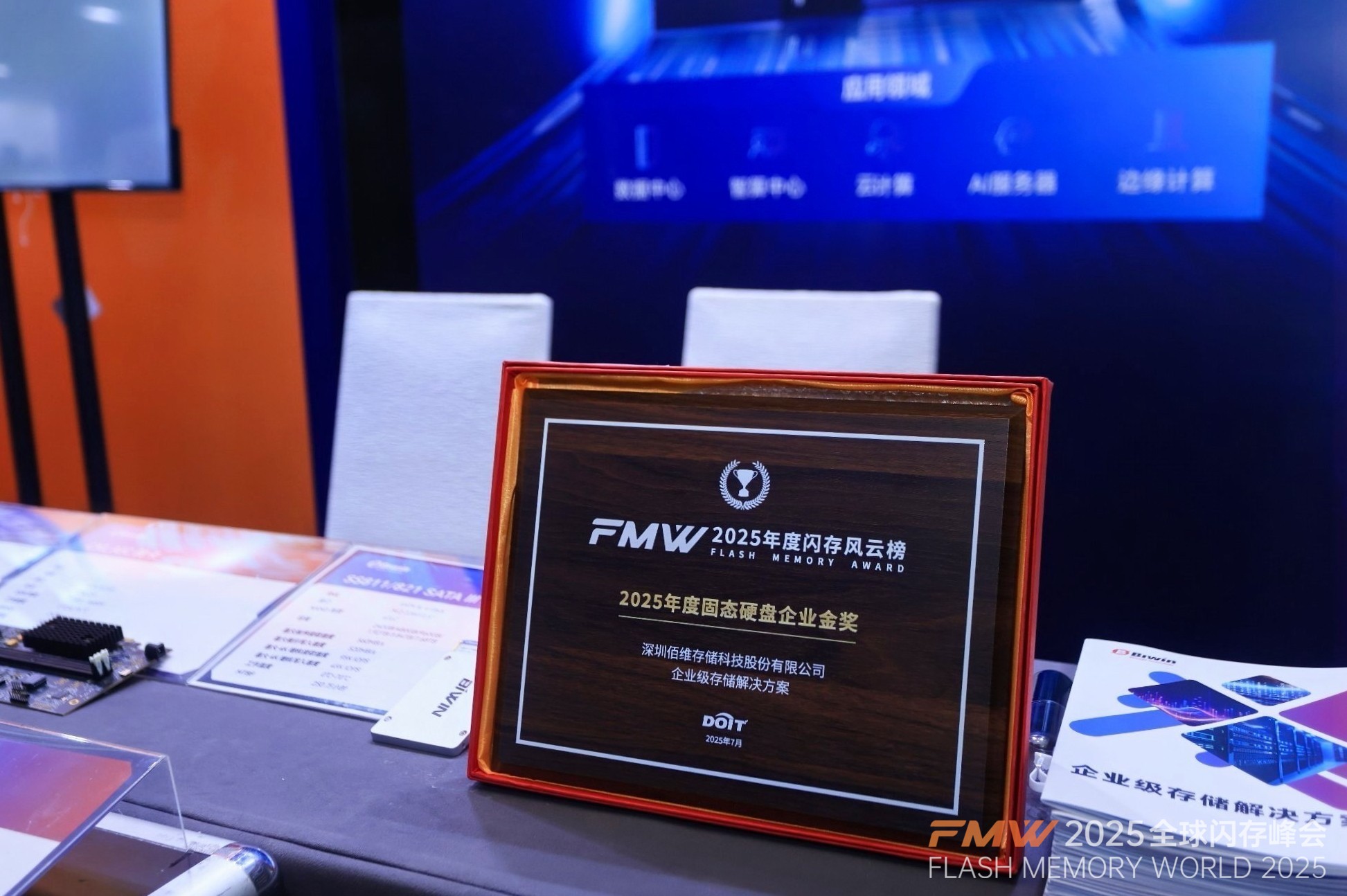
  Recently, BIWIN made a mark in the Flash Memory World 2025 hosted by DOIT, where it showcased its comprehensive enterprise-grade storage portfolio and was honored with the "Solid State Drive Enterprise Gold Award 2025." This recognition further underscores the company’s technical expertise and product excellence in the enterprise storage sector.  Focus on Enterprise Applications  Building a Product Ecosystem for Diverse Scenarios  The rapid growth of AI-driven computing has fueled increasing demand for high-performance, high-density SSDs and large-capacity memory solutions. BIWIN-launched enterprise-grade storage solutions cater to a wide range of applications, covering from traditional servers and data centers to AI servers and from cloud computing platforms to edge computing nodes. These products deliver exceptional performance and stability while meeting stringent customer requirements for data security, system compatibility, and long-term operational reliability.  SATA SSD: Designed for mainstream server platforms, SATA SSD offers high energy efficiency and low total cost of ownership (TCO) storage solutions.  PCIe SSD: Available in both Gen4 and Gen5 versions, PCIe SSDs are featured with high performance and low latency, making them ideal for high-performance computing scenarios like AI training, databases, and distributed storage.  CXL Memory Expansion Modules: Aligned with next-generation computing architectures, CXL modules support higher bandwidth and lower-latency memory access.  RDIMM Memory Modules: Tailored for server platforms, RDIMM modules provide large-capacity, high-stability memory for various high-end computing scenarios.  SP Series PCIe SSD  A Flagship Enterprise Solution Balancing Efficiency and Security  BIWIN’s SP Series enterprise-grade PCIe SSDs, available in PCIe 4.0 and PCIe 5.0 interfaces, address a wide range of performance requirements.  Featured with a PCIe 5.0 ×4 interface and a 2.5" U.2 form factor, the SP5 Series demonstrates exceptional throughput and responsiveness, capable of delivering sequential read/write speeds of up to 13,600 MB/s and 10,500 MB/s, and 4K random read/write performance up to 3,200K IOPS and 910K IOPS respectively. In addition, its innovative architectural design enables industry-leading KIOPS-per-Watt performance, providing strong support for the development of green data centers.  In AI training scenarios, key features such as large capacity, high speed and low latency offered by SP series SSDs contribute to significantly enhancing data training and computational efficiency for large-scale models; while in big data analytic systems, its capability to achieve high-concurrency access plays a large part in elevating critical business data processing efficiency, reducing response times and accelerating decision-making processes.  The SP Series also integrates advanced functionalities, including AES256 encryption, Sanitize advanced formatting, End-to-End Data Path Protection, Internal RAID, Secure Boot, and TCG Opal 2.0. These help to secure data security and integrity during transmission and storage, making it particularly suitable for applications with stringent data sensitivity requirements.  Technologies Empowers Market Expansion  Collaborating with Partners to Create Ecosystem Value  On the market side, the company’s enterprise-grade products have passed China Mobile’s AVAP test, as well as interoperability tests with over 20 CPU platforms and OEM manufacturers. Strategic partnerships have been established with multiple domestic platform vendors, and the company has also successfully passed audits by several leading internet companies. In terms of technical capabilities, the company boasts an experienced R&D team and holds a broad portfolio of core technology patents in Thermal Management, Wear Leveling, ECC, and Intelligent Storage Management Algorithms, which collectively strengthen the company’s leading role in cutting-edge storage technology.  Looking ahead, BIWIN will continue to strengthen its Integrated Solutions and Manufacturing (ISM) strategy while pursuing its “52X” mid-to-long-term strategy to enhance product competitiveness and ecosystem influence. With further collaborations with server OEMs, the company aims to advance joint development of high-performance storage solutions for AI and edge computing and deliver customized solutions tailored to customer needs. In parallel, efforts will be concentrated across key verticals, including telecom operators, top domestic internet platforms, and technical co-development initiatives. Through cross-sector collaboration in areas such as technical collaboration, industry applications, and co-development with customers, BIWIN aims to build an open, collaborative, and mutually beneficial ecosystem for enterprise-grade storage segment.
Key word:
Release time:2025-08-04 11:22 reading:557 Continue reading>>
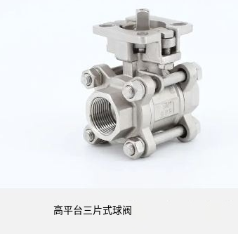
Tumfei Valve Technology:The principle of common valves and their use
  Tumfei Valve Technology has summarized the principle of common valves and their use. Let's learn about them together.  First, the role of the valve  1, opening and closing action - cut off or communicate the flow of fluid in the tube;  2, regulating effect - regulating tube flow, flow rate;  3, throttling effect - make the fluid through the valve to produce a large pressure drop;  4. Other functions -a. Automatic opening and closing b. Maintain a certain pressure c, prevent steam drainage.  Second, the type of valve  1, according to the use of: cut-off valves, regulating valves, diverting valves, check valves, safety valves;  2, according to the force points: he action with the valve, automatic action valve.  Three, the main parameters of the valve  PN nominal pressure (the maximum pressure that allows fluid to pass through);  DN nominal diameter;  TN Temperature range (permissible fluid temperature range).  Forth, Check the valve before use  Check items include:  1, the internal and external surfaces of the valve body have sand holes, cracks and other defects;  2. Whether the valve seat is firmly engaged with the valve body, whether the spool is consistent with the valve seat, and whether the sealing surface is defective;  3, whether the valve stem and the spool connection is flexible and reliable, whether the valve stem is bent, whether the thread is damaged or corroded;  4, packing, gasket is aging damage;  5, the valve open is flexible, etc.  Fifth,Problems often occur in the use of valves  1, flange and thread leakage at the connection of the pipeline;  2, packing culvert leakage, waist pad leakage and valve stem can not move;  3, between the valve core and the seat is not tightly closed to form internal leakage.  Sixth, the characteristics of commonly used valves and their use precautions  (1) Plug Valve (Cock)  Features: TN less than 150 degrees PN less than 1.6Mpa its simple structure, quick opening and closing, easy operation, low fluid resistance and other advantages  Precautions for use:  1, the outer end of the valve stem is square, the straight line marked by the diagonal is vertical and the direction of the valve body is closed, and the direction of the valve body is consistent with the open state;  2, the normal switch valve with cock special wrench, to avoid sliding with the valve stem caused by safety accidents; Try not to use an adjustable wrench to cause slippage;  3, open the valve according to the previous check item check, slowly open the valve after the check, try not to stand in the direction of the sealing surface when opening, encounter acid and alkali fluid must wear acid mask;  4, if the pipeline has a sight mirror see the fluid in the sight mirror can be checked and left.  (2) Ball valve:  Ball valve and plug valve are the same type of valve, but the opening and closing part is a ball with a hole, and the center line of the ball valve stem rotates to achieve the purpose of opening and closing.  Insulated ball valve with jacket  Stainless steel ball valve  Stainless steel ball valve quick opening ball valve  Features: Valve structure is simple, reliable, used for two-way flow medium pipeline, fluid resistance is small, good sealing; Disadvantages; The medium is easy to leak from the stem.  Precautions for use:  Same as a plug valve;  With a handle valve, the handle perpendicular to the medium flow direction for the closed state, consistent with the direction for the open state; If the ball valve with jacket insulation should pay attention to the following matters:  The jacket insulation steam should be opened to melt the crystallizing medium in the valve before opening and closing the valve, do not forcibly open and close the valve before the medium is completely melted;  When the valve cannot be opened, the method of lengthening the lever cannot be used to forcibly open the valve, because this will cause the valve stem to be resisted and the spool to fall off, causing damage to the valve or causing damage to the wrench, resulting in unsafe factors.  (3) Butterfly valve  The butterfly valve uses a rotating disc with a flexible shaft to control the opening and cosing of the pipeline, and the Angle size reflects the opening degree of the valve.  According to the different transmission methods, the butterfly valve is split, pneumatic and electric three, commonly used for manual, rotating handle through the gear drive valve stem to open and close the valve.  Features: Butterfly valve has the advantages of simple structure, rapid opening and closing, small fluid resistance, easy maintenance, etc., but it can not be used for high temperature and high pressure occasions, PN less than 1.6Mpa, t less than 120 degrees of large diameter water, steam, air, oil and other pipelines.  Precautions for use:  1, the spool can only be rotated 90 degrees, generally the valve body will indicate the direction of the CLOSE and OPEN arrows, the hand wheel clockwise rotation is closed, and the reverse is open;  2, if sometimes there is a certain resistance to opening and closing, you can use a special P wrench to open the valve. But it can not be forced to open and close, otherwise the male will stir the thin rod gear:  3. It is forbidden to remove the handwheel and report the hand vibration valve sample with activity; (Same goes for lower waist)  4. Gradually open and close when opening and closing, observe whether there is any abnormal situation, and prevent leakage.  (4) Stop valve  The globe valve is the most widely used cut-off valve in chemical production. Compared with the above three cut-off valves, it is not the use of the rotation of its closing parts to open and close the valve, but the use of the valve stem to drive the circular valve disc (valve head) connected with it, and change the distance between the valve disc and the seat to control the valve opening and closing.  Streamline type stop valve American standard stop valve  Features: The upper part of the globe valve has a handwheel, valve stem, the middle has a thread and packing culvert sealing section, the small valve stem on the thread in the valve body, its compact structure, but the valve stem and the medium contact part, especially the thread part is easy to corroded, from the height of the valve stem exposed to the valve cover can be judged  The globe valve structure is more complex, but the operation is simple, not very laborious, easy to adjust the flow rate and truncate the channel, slow closing without water hammer phenomenon, so it is more widely used.  When installing the globe valve, pay attention to the direction of the fluid, the pipeline fluid should flow through the valve seat from the bottom up, and the so-called "low into high", the purpose is to reduce the fluid resistance, so that the valve stem and packing culvert are not in contact with the medium under the opening and closing state, to ensure that the valve stem and packing culvert are not damaged and leaked.  The globe valve is mainly used for the pipeline of water, steam, compressed air and various materials, which can adjust the flow rate more accurately and strictly cut off the channel, but can not be used for materials with large viscosity and easy crystallization.  Precautions for use:  1, before opening to check the valve for defects, especially the filler culvert leakage:  2, in the valve stem can not be directly rotated by hand, the special F wrench can be used to open and close, when it is still unable to open and close, please do not extend the wrench lever to force open and close, resulting in damage to the valve or cause safety accidents:  3, when used for medium pressure steam pipeline valve, the condensate in the pipe should be drained first when opened. Then slowly open the valve with 0.2 to 0.3Mpa steam to preheat the pipeline, to avoid the sudden opening of pressure caused by damage to the sealing surface, called the normal inspection after the pressure to adjust the required state  (5) Gate valve  Gate valve, also known as gate valve or gate valve, it is through the lift of the gate to control the valve opening and closing, the gate is straight to the direction of the fluid, change the relative position between the gate and the seat can change the size of the channel.  Open stem gate valve Dark stem gate valve  According to the different movement of the valve stem when the gate valve is opened and closed, the gate valve has two kinds of distinct rod type and dark rod type.  Open rod gate valve stem thread strike outside the valve body, open the valve stem out of the handwheel, its advantage is that according to the length of the valve stem to determine the size of the valve open, the valve stem and the medium contact length is small, the thread part is basically not affected by the medium corrosion, the disadvantage is that the height of the overhang space.  The valve stem thread inside the valve stem and the internal thread on the gate plate want to match, open the valve stem only rotation without up and down, the gate rises along the valve stem thread. The advantage of dark rod gate valve is that the overhang space is small, the disadvantage is that the opening of the valve can not be judged according to the condition of the valve stem, and the valve stem thread is easily corroded by long-term contact with the medium.  Gate valve has the advantages of small fluid resistance, constant medium flow direction, slow opening without water hammer phenomenon, easy to adjust the flow rate, etc. The disadvantages are complex structure, large size, long opening and closing time, and difficult maintenance of sealing surface. Due to the large bore feed pipe  1, when the valve stem is opened and closed in place, it can not be forced to force, otherwise it will break the internal thread or latch screw, so that the valve is damaged;  2, open and close the valve when the hand can not be directly started, F wrench can be used to open and close;  3. When opening and closing the valve, pay attention to the sealing surface of the valve, especially the packing gland to prevent leakage.  (6) Throttle valve  Throttle valve, also known as needle valve, its shape is similar to the globe valve, its valve core shape is different, back to the base or parabola, often used in the instrument, often bundle connection.  Precautions for use:  1, because of the threaded connection, first check whether the threaded connection is loose when opening and closing;  2, open and close the valve slowly, because the flow area is small, the flow rate is large, may cause corrosion of the sealing surface, should pay attention to observe, pay attention to the change of pressure.  (7) Check valve  Check valve is a valve that automatically opens and closes by using the pressure difference between the medium before and after the valve to control the one-way flow of the medium, also known as check valve or check valve.  Check valves are divided into two types according to different structures: lifting type (jumping type) and swinging type (shaking pole type).  Lift type swing type  Precautions for use:  Pay attention to the direction of the valve, the arrow is consistent with the flow direction of the medium, such as the medium easy crystallization may cause the valve disc can not be pressed down to play the role of command and check.  (8) Safety valve  The safety valve is a kind of valve that automatically opens and closes according to the medium pressure. When the medium pressure exceeds a certain value, it can automatically open the valve to discharge pressure relief, so that the equipment pipeline is free from the danger of damage, and can automatically close after the pressure returns to normal.  According to the way of balancing the internal pressure, the safety valve is divided into two categories: lever weight type and spring type.  Precautions for use:  1, the safety valve must be used within the validity period;  2, the safety valve control valve installed on the pipeline and equipment is usually the globe valve must be opened to ensure that the safety valve can work effectively;  3. Periodically lift the valve disc slightly and use the medium to blow the impurities in the valve.  4, if the safety valve can not work within the setting pressure, it must be re-validated or replaced  (9) Steam trap  Steam trap is a kind of valve that can automatically and intermittently remove condensate and prevent steam from leaking out in steam pipeline, heater and other equipment systems. Commonly used are bell-shaped float type, thermal power type and pulse type.  Precautions for use:  1, use the pipeline bypass valve to remove condensate before use, when there is steam to close the bypass, start the trap path, otherwise the valve will be closed water can not play the role of drainage;  2. Be careful not to be scalded by steam when opening and closing the valve.  (10) All kinds of sampling valves  As the name suggests, the sampling valve is a valve used to obtain media samples so that chemical analysis can be performed, generally installed in equipment or pipelines are roughly divided into the following categories:  Double opening valves, flanged clip valves, and sampling valves with insulated jacket:  Use note method:  1, the double opening valve is generally composed of two ball valves, to sample safety and achieve the purpose of sampling through linkage in the negative pressure device; When sampling, close the second valve near the equipment and pipeline and open the first valve. Let the medium flow into the space between the two valves; Then close the first valve, open the second valve, and place the sampling vessel into the sampling port to contain the medium;  2. The flange clip valve is generally sealed through the top cone of the valve stem and the cone hole of the seat, and the valve stem is separated from the cone hole by turning the hand wheel during sampling, so that the medium can flow from the cone hole to the external sampling vessel;  3, with jacket insulation sampling valve should pay attention to the following matters:  I should open the jacket insulation steam to melt the crystallizable medium in the valve before opening and closing the valve, do not forcibly open and close the valve before the medium is completely melted;  When the valve cannot be opened, the method of lengthening the lever cannot be used to forcibly open the valve, because this will cause the valve stem to suffer greater resistance and the valve core to fall off, or cause the valve stem and the cone hole sealing surface to be damaged. from  And cause damage to the valve or cause damage to the wrench, resulting in unsafe factors.  (11) Fluorine plastic lined rubber valve  Fluorine plastic lined rubber valve is mainly used in acid and alkali and other corrosive media, its structure principle is similar to the unlined fluorine plastic valve, but its stem, valve core, valve seat are used fluorine plastic substrate, its use method is similar.  Classification of valves  There are many kinds of valves. With the continuous improvement of the process flow and performance of various complete sets of equipment, the types of valves are still increasing, and there are a variety of classification methods.  According to the automatic and drive classification, can be divided into:  1) Automatic valves rely on the ability of the medium (liquid, air, steam, etc.) to operate by itself. Such as safety valves, check valves, pressure reducing valves, steam traps, solenoid valves, air traps, emergency cut-off valves, etc.  2) Drive valves Valves that are operated manually, electrically, hydraulically or pneumatic. Such as gate valve, globe valve, throttle valve, butterfly valve, ball valve, plug valve and so on.  According to the use and function classification, can be divided into:  1) The cut-off valve is mainly used to cut off or connect the medium flow in the pipeline. Such as globe valve, gate valve, ball valve, plug valve, butterfly valve, diaphragm valve and so on.  2) Check valves are used to prevent the backflow of the medium. Such as a variety of different structures of the check valve.  3) Regulating valves are mainly used to regulate the pressure and flow of the pipeline medium. Such as regulating valve, throttle valve, pressure reducing valve and so on.  4) The diverter valve is used to change the direction of the flow of the medium in the pipeline, and plays the role of distributing, diverting or mixing the medium.  Such as various structures of distribution valves, three-way or four-way plug valves, three-way or four-way ball valves, various types of traps and so on.  5) Safety valves are used for overpressure safety protection, discharge of excess media, and prevent pressure from exceeding the specified value. Such as various types of safety valves.  6) Multi-purpose valves are used to replace two, three or even more types of valves. Such as stop check valve, check ball valve, stop check safety valve, etc.  7) Other special valves such as blowdown valve, blowdown valve, coke valve, pigging valve, etc.
Release time:2025-06-17 14:09 reading:649 Continue reading>>
ROHM Develops Class-Leading* Low ON-Resistance, High-Power MOSFETs for High-Performance Enterprise and AI Servers
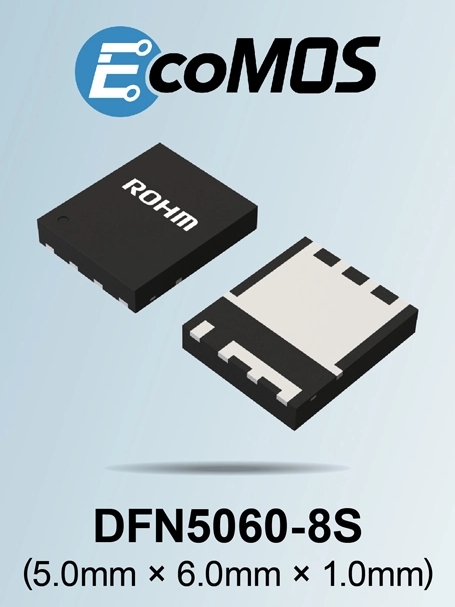
  ROHM has developed N-channel power MOSFETs featuring industry-leading* low ON-resistance and wide SOA capability. They are designed for power supplies inside high-performance enterprise and AI servers.  The advancement of high-level data processing technologies and the acceleration of digital transformation have increased the demand for data center servers. At the same time, the number of servers equipped with advanced computing capabilities for AI processing is on the rise and is expected to continue to grow. These servers operate 24 hours a day, 7 days a week – ensuring continuous operation. As a result, conduction losses caused by the ON-resistance of multiple MOSFETs in the power block have a significant impact on system performance and energy efficiency. This becomes particularly evident in AC-DC conversion circuits, where conduction losses make up a substantial portion of total power loss – driving the need for low ON-resistance MOSFETs.  Additionally, servers equipped with a standard hot-swap function, which allow for the replacement and maintenance of internal boards and storage devices while powered ON, experience a high inrush current during component exchanges. Therefore, to protect server components and MOSFETs from damage, a wide Safe Operating Area (SOA) tolerance is essential.  To address these challenges, ROHM has developed its new DFN5060-8S package that supports the packaging of a larger die compared to conventional designs, resulting in a lineup of power MOSFETs that achieve industry-leading* low ON-resistance along with wide SOA capability. These new products significantly contribute to improving efficiency and enhancing reliability in server power circuits.  The new lineup includes three products. The RS7E200BG (30V) is optimized for both secondary-side AC-DC conversion circuits and hot-swap controller (HSC) circuits in 12V power supplies used in high-performance enterprise servers. The RS7N200BH (80V) and RS7N160BH (80V) are ideal for secondary AC-DC conversion circuits in 48V AI server power supplies.  All three models feature the newly developed DFN5060-8S package (5.0mm × 6.0mm). The package increases the internal die size area by approximately 65% compared to the conventional HSOP8 package (5.0mm × 6.0mm). As a result, the RS7E200BG (30V) and RS7N200BH (80V) achieve ON-resistances of 0.53mΩ and 1.7mΩ (at VGS = 10V), respectively – both of which rank among the best in the industry in the 5.0mm × 6.0mm class, significantly contributing to higher efficiency in server power circuits.  Moreover, ROHM has optimized the internal clip design to enhance heat dissipation, further improving SOA tolerance, which contributes to ensuring application reliability. Notably, the RS7E200BG (30V) achieves an SOA tolerance of over 70A at a pulse width of 1ms and VDS = 12V, which is twice that of the conventional HSOP8 package MOSFETs under the same conditions, ensuring industry-leading SOA performance in a 5.0mm × 6.0mm footprint.  Going forward, ROHM plans to gradually begin mass production of power MOSFETs compatible with hot-swap controller circuits for AI servers in 2025, continuing to expand its lineup that contributes to greater efficiency and reliability across a wide range of applications.  Product Lineup  EcoMOS™ Brand  EcoMOS™ is ROHM's brand of silicon power MOSFETs designed for energy-efficient applications in the power device sector.  Widely utilized in applications such as home appliances, industrial equipment, and automotive systems, EcoMOS™ provides a diverse lineup that enables product selection based on key parameters such as noise performance and switching characteristics to meet specific requirements.  EcoMOS™ is a trademark or registered trademark of ROHM Co., Ltd.  Application Examples  ・AC-DC conversion and HSC circuits for 12V high-performance enterprise server power supplies  ・AC-DC conversion circuits for 48V AI server power supplies  ・48V industrial equipment power supplies (i.e. fan motors)  Terminology  Low ON-Resistance (RDS(on))  The resistance value between the Drain and Source of a MOSFET during operation. A smaller RDS(on) results in lower power loss during operation.  SOA (Safe Operating Area) Tolerance  The range of voltage and current within which a device can operate safely without damage. Exceeding this range can lead to thermal runaway or device failure, making SOA tolerance a critical factor, especially in applications prone to inrush current or overcurrent.  Power MOSFET  A type of MOSFET used for power conversion and switching applications. N-channel MOSFETs are the mainstream choice, as they become conductive when a positive voltage is applied to the gate relative to the source, offering lower ON-resistance and higher efficiency than P-channel variants. Due to their low loss and high-speed switching capabilities, power MOSFETs are widely used in power circuits, motor drive circuits, and inverters.  Hot-Swap Controller (HSC)  A specialized integrated circuit (IC) that enables hot-swap functionality, allowing components to be inserted or removed while the power supply system remains active. It plays a crucial role in managing inrush current that occurs during component insertion, protecting both the system and connected components from damage.  Inrush Current  A sudden surge of current that momentarily exceeds the rated value when an electronic device is powered ON. Proper control of this current reduces stress on power circuit components, helping to prevent device failure and stabilize the system.
Key word:
Release time:2025-04-10 13:10 reading:608 Continue reading>>
ROHM Develops a New Compact Thermal Printhead for A4-Sized Mobile Printers
  ROHM has developed a new thermal printhead - KA2008-B07N70A - compatible with a 2-cell Li-ion battery (7.2V). Designed to deliver high print quality with low power consumption and optimized for A4 size printers (210mm width). Height has been reduced by approximately 16% from the conventional 14mm to a best-in-class* 11.67mm – contributing to a more compact printer design. Moreover, optimizing the heating element structure while improving the driver IC and wiring layout enables the support for 7.2V operation – reducing the applied energy required for printing by approximately 66% compared to conventional 12V drive (at 50 mm/s print speed). Adjustments to the individual wiring of the resistive elements ensure uniform heat generation, stabilizing print quality and enabling sharp and high-resolution 203dpi printing – even at speeds up to 100 mm/s.  In recent years, the thermal printer market has been expanding in response to increasing demand to print qualified invoices and customs labels fueled by the growth of overseas e-commerce, as well as prescriptions and drug information sheets in hospitals and pharmacies. The demand for mobile printers has surged, particularly in the logistics and business sectors, where portability and ease of maintenance are highly valued. Among these trends, the adoption of A4-sized thermal printers has been growing in Asian markets, particularly in China – driving the need for 8-inch thermal printheads.  A4-sized mobile printers face challenges such as high power consumption due to their wider print width, requiring larger battery capacities compared to smaller printers such as receipt printers. Moreover, the need for multiple driver ICs to control the heating elements in A4-sized printers often results in variations in heat generation due to the differences in wiring lengths between elements, which affect print quality, such as color development and uniformity.  The KA2008-B07N70A addresses these challenges through an optimized design that enhances mechanical strength and durability by mitigating the effects of expansion and contraction caused by temperature changes. This meets the stringent durability requirements of A4-sized printers (the primary target market) while supporting both thermal and transfer printing methods – offering versatile printing for a wide range of applications.  While thermal printheads are typically used in combination with connectors and a heat sink, the KA2008-B07N70A can also be supplied as a standalone board, providing greater design flexibility for printer manufacturers. For inquiries regarding the product as part of a set, please contact AMEYA360 or visit the contact page on ROHM’s website.  Going forward, ROHM plans to develop a 300dpi resolution thermal printhead for mobile A4-sized printers by spring 2025. The company also intends to expand its considerable lineup with products that deliver high-speed printing with superior efficiency.  Key Specifications  For more information on printheads for mobile printers, please refer to the following URL on ROHM’s website: https://www.rohm.com/products/printheads/mobile-printers  Sales Information        Pricing: $14.50/unit (excluding tax)  Availability: Now (OEM quantities)  Application Examples        • A4-sized mobile printers  • Industrial control label printers  • Tattoo stencil printers, etc.  Terminology        dpi (dots per inch)  A unit of print resolution and density, indicating the number of dots that can be placed within a one-inch length (2.54 cm).  Thermal Printing Method  A printing technique in which heat is directly applied to thermal paper, causing a reaction that produces color. Primarily used for receipts and labels, this method eliminates the need for ink or toner, ensuring easy maintenance and operation.  Thermal Transfer Printing Method  A printing method in which heat melts ink coated on a ribbon, transferring it onto paper. Ideal for high-precision printing, it is commonly used for documents and labels requiring long-term preservation.
Key word:
Release time:2025-03-31 15:36 reading:411 Continue reading>>
Exploring Infrared Sensors: Types, Applications, and Principle
  In the realm of modern technology, infrared (IR) sensors stand out as versatile and essential components across a wide array of applications. These sensors leverage the infrared part of the electromagnetic spectrum to detect and measure infrared radiation, which can be indicative of heat, motion, and various other parameters. This article delves into the fundamentals of Infrared Sensors, and their diverse applications.  What is an infrared sensor ?Infrared sensors detect radiation in the infrared spectrum, which ranges from about 750 nanometers (nm) to 1 millimeter (mm). Unlike visible light, infrared radiation is not visible to the human eye but can be felt as heat. IR sensors convert this radiation into an electrical signal that can be processed and interpreted by electronic systems.  How many types of IR sensors are there?1. Active Infrared Sensors: These sensors emit their own infrared light and detect the reflected light. They are commonly used in proximity sensors and certain types of motion detectors. An example is the IR LED and photodiode pair, which measures changes in the reflected light to determine the presence of objects.  2. Passive Infrared Sensors (PIR): Unlike active sensors, PIR sensors do not emit any radiation. Instead, they detect the infrared radiation naturally emitted by objects. PIR sensors are widely used in motion detection applications, such as security systems and automatic lighting.  What is the purpose of the IR sensor?IR sensors serve various purposes across multiple applications. Here are some common uses:  1. Proximity Detection  – Used in devices like automatic doors, smartphones, and vehicles to detect nearby objects without physical contact.  2. Motion Detection  – Common in security systems and alarms (e.g., PIR sensors) to sense movement in a defined area.  3. Temperature Measurement  – Employed in non-contact thermometers to measure the temperature of objects or bodies from a distance.  4. Remote Controls  – Found in TVs, air conditioners, and other electronics to facilitate wireless communication with remote controls.  5. Obstacle Avoidance  – Used in robotics and drones to navigate and avoid collisions by detecting nearby objects.  6. Gas Detection  – Some IR sensors can detect specific gases based on their absorption of infrared light, useful in industrial applications.  7. Night Vision and Thermal Imaging  – Used in military, security, and surveillance applications to detect heat signatures in low-light conditions.  8. Data Transmission  – In certain applications, IR can be used for wireless data transfer over short distances.  What is an infrared sensor used for?Infrared sensors have a broad range of applications, benefiting various industries from consumer electronics to healthcare. Here are some notable examples:  1. Consumer Electronics:  – Remote Controls: IR sensors are integral to remote control devices for televisions, air conditioners, and other home appliances. They receive signals from the remote control unit to perform the desired function.  – Smartphones and Tablets: Some devices use IR sensors for facial recognition, which helps in unlocking screens and enhancing security.  2. Healthcare:  – Thermography: Infrared thermography is used for non-invasive temperature measurement, allowing for early detection of fevers and other medical conditions. It’s particularly valuable in monitoring patients’ health and in diagnosing conditions based on temperature anomalies.  – Vital Sign Monitoring: IR sensors can be used in wearable devices to monitor vital signs such as heart rate and blood oxygen levels.  3. Automotive Industry:  – Collision Avoidance Systems: IR sensors help in detecting obstacles and monitoring the surrounding environment to prevent accidents. They are used in parking assist systems and adaptive cruise control.  – Night Vision: Some high-end vehicles are equipped with IR sensors to enhance visibility during night driving by detecting pedestrians and animals on the road.  4. Industrial Automation:  – Temperature Measurement: In manufacturing processes, IR sensors are employed to monitor the temperature of machinery and products to ensure they remain within safe and optimal limits.  – Quality Control: These sensors are used to inspect products for defects and irregularities by detecting variations in thermal emission.  5. Environmental Monitoring:  – Gas Detection: IR sensors can detect the presence and concentration of specific gases in the atmosphere by measuring their absorption of infrared light. This is crucial for monitoring air quality and ensuring safety in industrial environments.  What is the principle of IR sensor?The principle of an infrared (IR) sensor is based on the detection and measurement of infrared radiation, which is electromagnetic radiation with wavelengths longer than visible light. The core principle involves capturing the infrared radiation emitted or reflected by objects and converting it into an electrical signal that can be analyzed. Here’s a detailed breakdown of how IR sensors work:  1. Emission and Detection of Infrared Radiation  Infrared Radiation Basics:  – Infrared radiation is part of the electromagnetic spectrum with wavelengths ranging from approximately 750 nanometers (nm) to 1 millimeter (mm), just beyond the visible light spectrum.  – All objects emit infrared radiation as a function of their temperature. Hotter objects emit more infrared radiation compared to cooler ones.  Detection Principle:  – Active IR Sensors: These sensors emit their own infrared light (often using an IR LED) and then measure the amount of this light that is reflected back from objects in their environment. The detected signal changes based on the distance, size, and properties of the object, allowing the sensor to infer its presence, distance, or other characteristics.  – Passive IR Sensors (PIR): These sensors do not emit any radiation. Instead, they detect the infrared radiation naturally emitted by objects in their field of view. They typically use a sensor element that responds to changes in infrared radiation, such as a pyroelectric detector or a thermopile.  2. Conversion of Infrared Radiation to Electrical Signal  Pyroelectric Detectors:  – Pyroelectric sensors contain materials that generate an electrical charge when exposed to infrared radiation. This charge is proportional to the amount of infrared radiation detected.  – The sensor detects changes in temperature caused by infrared radiation, converting these changes into an electrical signal.  Thermopiles:  – A thermopile consists of multiple thermocouples connected in series or parallel. It measures the temperature difference between the heated element exposed to infrared radiation and a reference element.  – This temperature difference generates a voltage, which is then measured and converted into an output signal.  Photodetectors:  – Some IR sensors use photodetectors (such as photodiodes or phototransistors) sensitive to infrared light. These detectors convert the incident infrared light into an electrical current proportional to the light intensity.  3. Signal Processing  Once the infrared radiation is converted into an electrical signal, the output is typically processed and analyzed by the sensor’s electronics. This may involve amplification, filtering, and digitization of the signal. The processed signal can then be used to trigger actions or provide readings depending on the application. For example:  – In motion detectors, the sensor might trigger an alarm if it detects significant changes in infrared radiation indicating movement.  – In temperature measurement systems, the signal is used to provide accurate temperature readings or to monitor thermal conditions.  How do I choose an IR sensor?Choosing an infrared (IR) sensor depends on several factors related to your application. Here’s a quick guide to help you make the right choice:  1. Type of IR Sensor  – Active IR Sensors: Emit IR light and measure reflections (e.g., proximity sensors).  – Passive IR Sensors: Detect IR radiation from objects (e.g., PIR sensors for motion detection).  2. Detection Range  – Consider the distance over which you need to detect objects. Check the specifications for range and field of view.  3. Sensitivity  – Look for specifications on sensitivity, which determines how small a change in IR radiation the sensor can detect.  4. Environmental Conditions  – Ensure the sensor can operate in the conditions it will face (temperature, humidity, dust, etc.).  5. Response Time  – Consider how quickly the sensor needs to respond. This is crucial for applications like motion detection.  6. Output Type  – Decide whether you need digital output (on/off) or analog output (variable signal) based on how you’ll process the sensor data.  7. Power Consumption  – Look for power-efficient models if you’re running on batteries or need to minimize energy use.  8. Size and Form Factor  – Ensure the physical size and mounting options fit your project requirements.  9. Cost  – Determine your budget, as prices can vary widely based on features and capabilities.  10. Manufacturer Support  – Choose brands or suppliers that provide good documentation and support.  How far can IR sensors detect?The detection range of IR sensors can vary significantly based on the type of sensor and its design:  1. Active IR Sensors  – Proximity Sensors: Typically have a range of a few centimeters to a few meters (around 0.1 to 5 meters) depending on the sensor’s power and environment.  – IR Range Finders: Can detect distances up to 10-20 meters or more, depending on the model and application.  2. Passive IR Sensors (PIR)  – Commonly used for motion detection in security systems, these sensors usually have a range of about 5 to 12 meters (16 to 40 feet). The actual range can be influenced by factors such as the angle of detection and the presence of obstacles.  3. IR Cameras and Thermal Sensors  – These devices can detect heat signatures at much greater distances, often exceeding 100 meters, depending on the resolution and the environment.  Factors Influencing Range  – Sensitivity: Higher sensitivity allows for detection at greater distances.  – Environmental Conditions: Obstructions, temperature, and humidity can affect performance.  – Field of View: A wider field of view may reduce the effective detection range.  ConclusionInfrared sensors are indispensable components in modern technology, offering critical functionalities across various fields. From enhancing consumer electronics to advancing healthcare and industrial automation, their applications are both diverse and impactful. As technological advancements continue to push the boundaries of what is possible, IR sensors are poised to become even more integral to our everyday lives, driving innovations and efficiencies across multiple sectors. Understanding their technology and applications provides valuable insights into how these sensors are shaping the future of technology and industry.
Key word:
Release time:2025-03-21 13:17 reading:496 Continue reading>>
Power Module : Working Principle, Structural Features, and Process
  A power module is an electronic device used to convert one form of electrical energy into another for supply to specific electronic systems or devices. It typically comprises an input terminal for receiving the raw power source (such as AC or DC) and one or more output terminals for providing converted and regulated electrical energy. This article summarizes the working principle, structural features, process flow, selection parameters, and design considerations of power modules.  Working Principle of Power ModuleThe working principle of a power module is based on power electronics technology and control circuitry. Its core consists of switching power devices and control circuits. The following are detailed operational steps of power module operation:  1. Input Voltage Conversion  The power module first receives input voltage from the power line, typically AC.  Next, through rectification circuitry using diodes or bridge rectifiers, AC is converted into pulsating DC.  Subsequently, filtering circuits utilize capacitors to remove the pulsation, resulting in stable DC.  2. Output Voltage Regulation  The converted DC enters a voltage regulation circuit for voltage regulation.  The voltage regulation circuit operates using feedback control. Specifically, it compares the difference between the output voltage and a reference voltage and controls the regulator’s operation based on this difference.  Through this regulation, the output voltage is maintained at the set stable value.  3. Role of Switching Power Devices  During the power conversion process of the power module, switching power devices (such as MOSFETs, BJTs, IGBTs, etc.) play a crucial role.  When the switching device is conducting, the power module can convert input energy into output energy. The primary function of the switching device is to achieve intermittent energy conversion to provide the required stable voltage or current.  When the switching device receives an input or control signal, it generates corresponding switch signals to control its state.  4. Role of Control Circuits  Control circuits are another important component of the power module responsible for precise regulation and stabilization.  Feedback circuits monitor changes in output voltage or current and send feedback signals to comparators. This allows the power module to adjust output energy promptly based on the feedback signal to meet various circuit requirements.  5. Protection Mechanisms  Power modules typically feature various protection mechanisms such as overload protection, overvoltage protection, and short circuit protection.  Overload protection monitors the output current and limits or cuts off the output when the current exceeds a set value.  Overvoltage protection monitors the output voltage and automatically cuts off the output power when the voltage exceeds a set value.  Short circuit protection similarly operates by monitoring the output current. When a short circuit is detected, it promptly cuts off the power to prevent damage.  Structural Features of Power ModuleThe structural features of power modules are summarized as follows:  1. Modular Design  Power modules typically employ modular design, making the entire power system more compact and efficient. Each module has independent functionality, allowing for flexible combinations and extensions based on actual needs. This facilitates users in customizing power solutions according to specific application scenarios.  2. High Integration  Power modules integrate numerous electronic components and circuits internally, such as transformers, rectifiers, and filters. The optimized design of these components and circuits endows the power module with high efficiency and stability.  3. High Reliability  Power modules undergo rigorous production processes and quality control, resulting in high reliability. Additionally, internal redundancy design and protection circuits effectively prevent damage to the system due to abnormal conditions such as power fluctuations, overcurrent, and overvoltage.  4. Ease of Maintenance  Due to the modular design of power modules, when a fault occurs, users can conveniently replace the faulty module, thereby reducing maintenance costs and time. Furthermore, the modular structure facilitates upgrades and modifications to the power system.  Process Flow of Power ModuleThe production process of power modules involves multiple steps, from material preparation to final testing and quality inspection, with each step being crucial. Below is a simplified description of the operation process of power module production:  1. Material Preparation and Bill of Materials (BOM) Verification  Based on the design drawings of the power module and the BOM (Bill of Materials) list, prepare the required components, PCB boards, connecting wires, insulation materials, etc.  Check the quantity, model, and specifications of the materials to ensure accuracy.  2. PCB Board Processing and Component Soldering  Clean and dry the PCB board to remove surface stains and moisture.  According to the design drawings, solder the components onto the PCB board. Pay attention to soldering temperature and time control to avoid solder joints or poor soldering.  3. Power Circuit Connection and Insulation Processing  Based on the circuit diagram of the power module, connect the power input and output lines.  Insulate exposed wires and connection points to ensure safety.  4. Functional Testing and Performance Debugging  Conduct functional testing on the power module to check if input and output voltage and current are normal.  Based on the test results, perform performance debugging to optimize the efficiency of the power module.  5. Overall Assembly and Enclosure Installation  Assemble the soldered PCB board, connecting wires, and other components into a complete power module.  Install the enclosure of the power module to ensure reliable fastening.  6. Final Testing and Quality Inspection  Conduct final testing on the assembled power module, including voltage stability, ripple coefficient, load capacity, and other indicators.  According to quality inspection standards, screen and classify the power modules to ensure product quality.  7. Packaging and Warehouse Entry  Package the qualified power modules, indicating model, specifications, quantity, etc.  Store the packaged power modules in the warehouse, awaiting shipment or subsequent use.  Selection Parameters of Power ModuleDuring the process of selecting power modules, it is essential to consider a series of key parameters to ensure that the chosen power module can meet specific application requirements. Below is a detailed consideration of these parameters:  1. Input Voltage Range  Firstly, it is necessary to determine the input voltage range of the power module, i.e., the range within which it can operate normally. This depends on the power supply situation in the application, such as battery-powered or AC grid-powered. Ensure that the selected module can adapt to the existing input voltage and maintain stability during voltage fluctuations.  2. Output Voltage and Current  The output voltage and current of the power module are critical parameters to meet load requirements. Depending on the power consumption and characteristics of the load, choose appropriate output voltage and current levels. Also, consider whether the current output capacity of the power module is sufficient to handle the startup impact of the load and the current requirements during normal operation.  3. Efficiency and Power Consumption  Efficiency is the ability of the power module to convert electrical energy, i.e., the ratio of output power to input power. High efficiency means less energy loss and lower heat generation. Additionally, pay attention to the module’s power consumption, especially during standby or light load, to optimize energy use.  4. Ripple and Noise  Ripple refers to the AC component in the output voltage, while noise is the interference signal generated by the power module. These parameters are crucial for sensitive applications such as signal processing or measurement equipment. Therefore, when selecting, ensure that the ripple and noise levels of the selected module are below the system’s acceptable threshold.  5. Temperature Range  The operating temperature range of the power module is also a factor to consider. In extreme temperature environments, the performance and reliability of the module may be affected. Therefore, choose a module that can operate stably within the temperature range of the application.  6. Reliability and Lifespan  The reliability and expected lifespan of the power module are important indicators for assessing its long-term performance. When choosing, consider the module’s MTBF (Mean Time Between Failures) and the manufacturer’s provided warranty period.  7. Size and Packaging  The size and packaging of the power module are also factors to consider during the selection process. Ensure that the selected module can fit within the space constraints of the application and is easy to integrate into existing systems.  8. Certification and Compliance  The selected power module should comply with relevant safety standards and regulatory requirements, such as UL, CE, etc. This helps ensure the safety and compliance of the power module.  9. Cost  Last but equally important is cost consideration. While meeting all performance requirements, strive to choose a cost-effective power module to optimize the overall cost-effectiveness of the system.  During the design and use of power modules, the following operational issues should be noted:I. Design Phase Considerations1. Clarify Requirements and Specifications  Before designing the power module, clarify the system’s requirements for power, including voltage, current, power, efficiency, and other specifications.  Fully consider the working environment of the module, such as temperature, humidity, vibration, and other factors that may affect the performance of the power supply.  2. Select Appropriate Topology  Choose the appropriate power supply topology according to the requirements, such as linear power supply, switching power supply, etc., to achieve high efficiency, stability, and reliability.  3. Optimize Circuit Layout and Wiring  Reasonably layout circuit components to reduce interference and losses.  Adopt the principle of wide and short wiring to reduce resistance and inductance, thereby improving power supply efficiency.  4. Redundancy and Protection Design  Consider redundancy design for the power module to improve system reliability and stability.  Design overvoltage, overcurrent, overheating, and other protection measures to prevent module damage or safety accidents.  5. Electromagnetic Compatibility (EMC) Design  Consider the electromagnetic compatibility of the power module and use filtering, shielding, and other technologies to reduce interference with other devices.  II. Considerations During Use1. Proper Installation and Connection  Follow the manufacturer’s installation guide to ensure the power module is installed correctly and securely fixed.  Carefully inspect the connections of input and output terminals to ensure good contact, no looseness, or short circuits.  2. Adjust Parameters Reasonably  According to actual needs, set the voltage, current, and other parameters of the power module reasonably to avoid overloading or underloading.  Regularly check parameter settings to ensure consistency with actual requirements.  3. Monitoring and Maintenance  Regularly conduct status checks on the power module, including monitoring parameters such as voltage, current, and temperature.  If any abnormal conditions are detected, take timely measures to address them, such as cleaning dust or replacing damaged components.  4. Heat Dissipation and Working Environment  Pay attention to the impact of electromagnetic interference and mechanical vibration in the working environment on the power module and take corresponding measures for protection.  5. Training and Operational Standards  Provide training for personnel using the power module to ensure they understand the working principle, operation methods, and safety precautions of the module.  Establish operational standards to ensure that personnel operate in accordance with the standards, avoiding problems caused by improper operation.
Release time:2024-08-22 13:33 reading:733 Continue reading>>
Temperature Sensor : Types, Applications, Working Principle and Much More
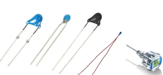
  A temperature sensor is a vital component in many systems where monitoring or controlling of temperature is required.  It allows one to measure the temperature of an object or environment and provide thermal data which is further used by various devices and applications.  Temperature sensors play an important role across many industries from automotive and medical to consumer appliances.  What is a temperature sensor?A temperature sensor is a device that helps in measuring the temperature of its environment, object or substance and converts the measurement into an electronic signal.  This electronic signal is further processed by auxiliary instrumentation such as temperature indicators, temperature controllers and temperature recorders to display or use the temperature data.  There are various types of temperature sensors available based on different sensing technologies like thermistor, thermocouple, Resistance Temperature Detector (RTD) etc.  What are different types of temperature sensors?Some of the common types of temperature sensors are:  Thermocouple  A thermocouple is a temperature sensor made by joining two different conductors at their ends to form a thermocouple junction. The voltage produced is dependent on the temperature difference between the thermocouple junction and a reference junction. Thermocouples are inexpensive, rugged and can measure a wide range of temperatures.  Resistance Temperature Detector (RTD)  An RTD is made up of a pure metal like platinum, copper or nickel which exhibits change in electrical resistance when exposed to change in temperature. The resistance increases linearly as temperature rises which makes it easy to convert to temperature using a simple formula. RTDs provide good accuracy over a wide temperature range.  Thermistor  A thermistor is a type of resistor whose resistance varies significantly with temperature changes. It exhibits a non-linear but known resistance-to-temperature relationship. Negative temperature coefficient (NTC) thermistors decrease in resistance with rising temperature while positive temperature coefficient (PTC) thermistors increase in resistance. They provide high accuracy and fast response time.  Integrated Circuit Sensor  An integrated circuit temperature sensor consists of a temperature sensitive circuit integrated onto a silicon chip that outputs voltage proportional to sensed temperature. They are small in size, inexpensive and mass producible. But accuracy is less as compared to other sensor types.  Infrared Sensor  Infrared sensors detect infrared energy radiated from an object or surface and produce an electronic signal proportional to the temperature. They are contactless and suitable to measure temperature without disturbing the environment but have less accuracy.  What are the advantages and disadvantages of temperature sensors?Advantages  • Provide accurate and repeatable temperature measurements.  • Respond quickly to temperature variations.  • Can measure a wide range of temperatures from below zero to thousands of degrees Celsius depending on type.  • Rugged, withstand vibrations and withstand hostile environmental conditions like humidity and pressure.  • Low cost options available for general purpose temperature measurements.  • Integrated circuit temperature sensors are small, mass producible and inexpensive.  Disadvantages  • Contact sensors disturb the medium whose temperature is being measured.  • Thermocouples produce small voltage signals requiring amplification.  • Response time of temperature sensors depends on thermal mass and insulation which limits fast temperature tracking.  • Temperature sensors have limited lifespan and require calibration over time.  • Special sensors are needed for measuring ultra-low or ultra-high temperatures.  How important is a temperature sensor?  A temperature sensor plays a vital role in maintaining quality and safety standards across many industries.  Some key applications where temperature sensors are mission critical include:  • Medical equipment and patient monitoring – Ensures safe temperatures for drug infusion, surgical/therapy devices, incubators etc.  • Automotive – Monitors engine temperature, fuel systems, brake fluid, transmission oil, exhaust gas recirculation.  • Industrial manufacturing – Controls processes in plastics molding, food processing, chemical reactions requiring specific temperatures.  • HVAC equipment – Essential component in thermostats, air conditioners, refrigerators to regulate temperatures.  • Fire/overheat detection – Prevents accidents by triggering alarms when abnormal high temperatures detected.  • Consumer appliances – Maintains safe cooking temperatures in ovens/stoves, cool temperatures in refrigerators.  Where are temperature sensors used?Industrial applications  Oil and gas plants to monitor pipeline temperatures, boiler temperatures.  Pulp and paper industry for dryer skin temperatures, consistency measurements.  Power plants to monitor transformer temperatures, boiler steam temperatures.  Iron and steel industry for molten metal temperatures, annealing furnace controls.  Automotive  Engine coolant temperature sensor in radiator.  Intake air temperature sensor.  Exhaust gas temperature sensor before catalytic converter.  Transmission fluid temperature sensor.  Rear differential and transfer case temperature sensors.  Medical  Patient thermoregulation- temperature probes in incubators, warming blankets.  Medical sterilizers- monitors autoclave temperatures.  Hyperthermia therapy- controls localized temperature increases.  HVAC  Thermostat temperature sensor  Duct-mounted temperature sensors  Outdoor temperature sensors  Household appliances  Refrigerator/freezer temperature sensors  Oven temperature sensors  Water heater thermostats  What is the difference between thermal sensor and temperature sensor?The main difference between a thermal sensor and a temperature sensor are:  Thermal sensors detect heat without direct contact while temperature sensors measure temperature through properties like resistance that change with temperature.  Thermal sensors provide relative heat indication without units while temperature sensors provide measured temperature output in units like Celsius or Fahrenheit.  How do temperature sensors work?Temperature sensors function based on different working principles depending on the sensing technology used:  Thermistors  Thermistors are made from semiconductor materials that change resistance predictably with temperature changes. As temperature rises, the mobility of charge carriers in the semiconductor increases resulting in lower electrical resistance that can be measured.  Thermocouples  When two different conductors are joined together, a voltage is produced dependent on their Seebeck coefficient and the temperature difference between the junction and reference junction. The output voltage is linearly proportional to temperature and is measured.  RTDs  Resistance Temperature Detectors use metals like platinum that change resistance reliably with temperature. Resistance increases linearly as temperature rises following PRT (Platinum Resistance Thermometers) or ITS-90 standard curves.  Integrated circuits  Complementary metal–oxide–semiconductors (CMOS) and bipolar transistors on an IC change current or voltage levels proportionally to temperature which is output analog or digital signals.  Infrared sensors  Infrared sensors contain a detector which absorbs infrared radiation from the target. The absorbed IR energy causes the detector temperature to rise above ambient. This temperature change alters the electrical properties to provide an output signal related to target temperature.  How to design a temperature sensor?  The steps involved in designing a temperature sensor are:  1. Select sensing element material based on required temperature range, accuracy, response time etc. like RTD, thermistor etc.  2. Design sensor probe matching application requirements like immersion, surface, air temperature sensing.  3. Choose appropriate housing material that withstands application environment. Consider thermal insulation, heat transfer etc.  4. Design signal conditioning circuitry to convert sensor output to standardized signals compatible with instruments like amplifiers, filters, transmitters etc.  5. Develop calibration curves and apply compensation algorithms in microcontroller if required for high accuracy.  6. Implement temperature scaling and linearization if needed in firmware or hardware.  7. Add optional features like remote sensor with transmission line, displays, alarms, microprocessor integration.  8. Test prototype under standard reference temperatures for calibration, accuracy, repeatability.  9. Enhance product through validation testing under field conditions, certifications.  10. Prepare design documentation for manufacturing.  What is the range of a temperature sensor?Temperature sensors can measure a wide range of temperatures based on the sensing technology and construction. Some common measurement ranges are:  • Thermocouples: -250°C to 1350°C  • RTDs: -200°C to 650°C  • Thermistors: -55°C to 150°C  • Integrated circuits: -55°C to 150°C  • Infrared sensors: -50°C to 500°C  Special types of sensors further extend the limits to measure very low cryogenic temperatures below -200°C for applications like liquified natural gas plants, high energy physics labs.  Similarly, special metallurgical thermocouples and optical pyrometer sensors go up to 3000°C for processes like steel making, glass welding.  ConclusionAn accurate and reliable temperature sensor is fundamental for process and quality control across major industries due to its role in monitoring, regulating and safety applications.  Understanding sensor types, principles, design and selection based on application demands is key.  Advancing technologies are continuously improving sensing capabilities to wider ranges, higher precisions and intelligent outputs.  As temperature measurement takes a more vital role, evolution of sensors will keep pace with the emerging trends.
Release time:2024-07-10 13:19 reading:785 Continue reading>>
GigaDevice Launches Advanced PC Fingerprint Solution, Promising Enhanced Security and User Experience
  a leading provider of flash memory, 32-bit microcontrollers, sensors, and analog technology, introduces all-new PC fingerprint solutions, including GSL6186 MoC(Match-on-Chip) and GSL6150H0 MoH(Match-on-Host). Based on advanced biometric technology, the solutions allow users to effortlessly and securely access their Windows PC devices with a simple touch of fingerprint. The GSL6186 MoC solution has already received certification from Windows Hello Enhanced Sign-in Security (ESS) and Microsoft Windows Hardware Lab Kit (HLK), added to Microsoft Approved Vendor List (AVL).  GigaDevice GSL6186 MoC fingerprint recognition solution utilizes System-in-package (SiP) technology, integrating fingerprint algorithm acceleration modules and storage modules within the chip. It combines excellent capacitive fingerprint hardware detection with proprietary algorithms, achieving an impressive high performance. The SiP system-level packaging ensures secure storage, minimizing privacy risks. Supporting POA and low latency, it enhances user experience and offers compatibility with USB, SPI interfaces, and various host platforms. Customizable in size and shape, it caters to diverse design preferences. Ideal for unlocking, system/APP software login, online payments, and various other scenarios, it delivers a convenient user experience.  GigaDevice GSL6150H0 MoH fingerprint recognition solution also comes equipped with high-performance capacitive fingerprint sensors and proprietary biometric algorithms. Utilizing on-host fingerprint matching, it provides a cost-saving advantage.  "We are committed to innovating in the next generation of intelligent terminal biometric sensing technology, delving into the research and development of human-machine interaction sensor chips and solutions", says Jun Zhi, Vice President and General Manager of Sensor BU in GigaDevice, "Our fingerprint products have become a popular selection in the smartphone market. The introduction of GSL6186 MoC and GSL6150H0 MoH signifies our further expansion into the PC domain. Regarding quality control, we are committed to delivering high-quality products and solutions to our customers, prioritizing comprehensive product lifecycle management and proactive risk control, alongside continuous process optimization. We have also established a stable and flexible supply chain system, which enables a quicker response to customer needs, enhancing the accuracy and timeliness of delivery.      Furthermore, we offer integrated services and technical support, providing a convenient 'one-stop' solution to expedite customers' product launch process. We will accelerate product upgrades and continue to expand our presence in fields such as PC, smartphones, wearables, mobile health, IoT, etc., offering customers a broader array of innovative solutions."
Key word:
Release time:2024-05-27 16:17 reading:1710 Continue reading>>
ROHM Develops Automotive Primary LDOs: Leveraging Original QuiCur™ Technology to Achieve Industry-Leading* Load Response Characteristics
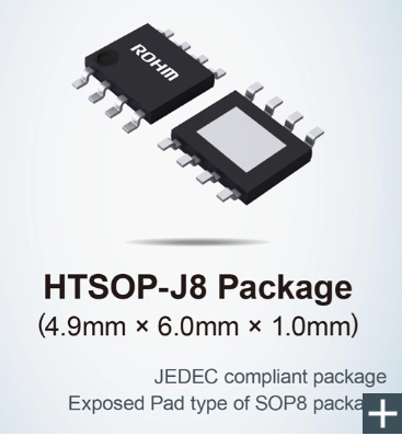
  ROHM has developed 45V rated 500mA output primary LDO regulators: BD9xxM5-C (BD933M5EFJ-C / BD950M5EFJ-C / BD900M5EFJ-C / BD933M5WEFJ-C / BD950M5WEFJ-C / BD900M5WEFJ-C). These devices are suitable for supplying power to automotive electronic components such as ECUs that operate from vehicle batteries.  In recent years, the number of onboard power supply system and functions continues to grow as electrification in the automotive industry progresses. This increases the demand for primary LDOs that can directly step down the battery voltage to MCUs and other components used in ECUs. However, the energy supplied by the vehicle’s lead-acid battery is often subject to sudden voltage fluctuations, which primary LDOs are required to provide with excellent line-transient response in these conditions.  At the same time, ECUs and other downstream devices often experience load current variations during operation, that also demand excellent load-transient response characteristics. A high frequency response is essential for fast output voltage recovery, but it has been difficult to provide sufficient phase margin at the same time to ensure stable operation. In response, ROHM developed a novel solution that addresses these challenges.  The BD9xxM5-C incorporates original QuiCur™ high-speed load response technology that delivers excellent response characteristics to load current fluctuations. For example, the LDO can maintain output to within 100mV of set voltage even as the load changes between 0 and 500mA in 1μs (Rise time/Fall time). Furthermore, low 9.5µA (typ.) current consumption contributes to lower power consumption in automotive applications. These new products will be available in four packages, ranging from the compact HTSOP-J8 to the high heat dissipation TO252 (TO252-3/TO252-5) and HRP5 types. This allows users to select the most suitable package for each use case.  Going forward, ROHM will continue to improve reliability while reducing power consumption in automotive applications by developing products utilizing its strengths in analog and other technologies.  Product LineupThe new BD9xxM5-C meets the basic requirements for automotive products, including 150°C operation and qualification under the AEC-Q100 automotive reliability standard. A wide range of packages will be available to select from depending on the application environment, all featuring excellent response performance and low current consumption using proprietary QuiCur™ technology.  The lineup will be expanded to comprise a total of 18 models, (including the TO252-3, TO252-5, and HRP5 packages) by FY2024.  Application ExamplesSuitable for a wide range of automotive applications such as ECUs that operate on vehicle primary power supply systems.  • Powertrain: Fuel Injection (FI), Tire Pressure Monitoring System (TPMS)  • Body systems: Body Control Modules  • Infotainment: Instrument Clusters, Head-Up Displays (HUDs)  QuiCur™ High-Speed Load Response TechnologyQuiCur™ is the name of ROHM’s proprietary ‘Quick Current’ high-speed load response circuit capable of maximizing load response characteristics (response performance) without causing instability in the feedback circuits of power supply ICs.  Stable operation of the power supply IC is also possible with minimal output capacitance. And in the case of switching regulators, which are a type of power supply IC, it is possible to linearly adjust the capacitance and output voltage fluctuation to easily achieve stable operation even when the capacitance is changed due to specification changes, significantly reducing the number of person-hours required for power circuit design - both in terms of decreasing component count and ensuring stable operation.  Click on the URL below for more information on QuiCur™ Technology.  https://www.rohm.com/news-detail?news-title=rohm-establishes-quicur-that-maximizes-the-response-performance-of-power-supply-ics&defaultGroupId=false  • QuiCur™ is a trademark or registered trademark of ROHM Co., Ltd.  Support ToolsROHM Real Models are high accuracy SPICE models that utilize original model-based technology to faithfully reproduce the electrical and temperature characteristics of the actual IC, resulting in a perfect match between the IC and simulation values. This ensures reliable verification, contributing to more efficient application development - for example by preventing rework after prototyping.  ROHM Real Models are now available on ROHM’s website (see link below).  https://www.rohm.com/products/power-management/linear-regulators/single-output-ldo-regulators?page=1&PS_ProductSeries=BD9xxM5%20series&PS_SpiceLink=1.0#parametricSearch  Online Sales InformationSales Launch Date: February 2024  Pricing: $1.5/unit (samples, excluding tax)  Online Distributors: DigiKey, Mouser and Farnell  The products will be sold at other online distributors as well.  Applicable Part Nos: BD950M5EFJ-C, BD933M5WEFJ-C, BD950M5WEFJ-C, BD900M5WEFJ-C  TerminologyPrimary  In a power supply circuit, the side in charge of 1st stage conversion from a power source such as a battery is called the primary and the side responsible for 2nd stage conversion referred to as the secondary.  LDO Regulator (Low Drop Out/Low Saturation Regulator)  A type of power supply IC that converts between two different DC voltage levels. Falls under the category of linear regulator (where the input/output voltages operate linearly) characterized by a small input-output voltage difference. Compared to DC-DC converter ICs (switching regulators), LDOs feature a simpler circuit configuration and lower noise.  Load Current  From the point of view of the power supply ICs, all electronic circuits in the subsequent stages, including MCUs and sensors, can be considered “loads”. When these loads operate, a (load) current flows, causing the output voltage of the power supply IC to undershoot (drop) or overshoot. Load transient response characteristics refer to the response time until the changed voltage due to load current is restored and the power supply stabilizes.
Key word:
Release time:2024-03-27 11:07 reading:684 Continue reading>>

Turn to

/ 9

  • Week of hot material
  • Material in short supply seckilling
model brand Quote
TL431ACLPR Texas Instruments
BD71847AMWV-E2 ROHM Semiconductor
CDZVT2R20B ROHM Semiconductor
RB751G-40T2R ROHM Semiconductor
MC33074DR2G onsemi
model brand To snap up
IPZ40N04S5L4R8ATMA1 Infineon Technologies
ESR03EZPJ151 ROHM Semiconductor
STM32F429IGT6 STMicroelectronics
BP3621 ROHM Semiconductor
TPS63050YFFR Texas Instruments
BU33JA2MNVX-CTL ROHM Semiconductor
Hot labels
ROHM
IC
Averlogic
Intel
Samsung
IoT
AI
Sensor
Chip
About us

Qr code of ameya360 official account

Identify TWO-DIMENSIONAL code, you can pay attention to

AMEYA360 mall (www.ameya360.com) was launched in 2011. Now there are more than 3,500 high-quality suppliers, including 6 million product model data, and more than 1 million component stocks for purchase. Products cover MCU+ memory + power chip +IGBT+MOS tube + op amp + RF Bluetooth + sensor + resistor capacitance inductor + connector and other fields. main business of platform covers spot sales of electronic components, BOM distribution and product supporting materials, providing one-stop purchasing and sales services for our customers.

Please enter the verification code in the image below:

verification code