ROHM’s New General-Purpose Chip Resistors Contribute to Greater Miniaturization
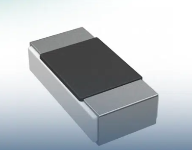
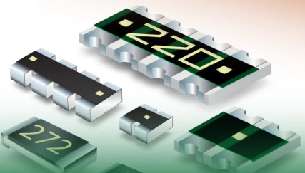
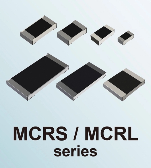
  ROHM has expanded its portfolio of general-purpose chip resistors with the MCRx family. It is designed to achieve greater miniaturization and enhanced performance across a variety of applications. The new lineup includes the high-power MCRS series and low-resistance, high-power MCRL series.  In today's era of advancing functionality and electrification, the increased miniaturization and improved performance of electronic components have become critical issues. This is especially evident in the automotive market, where the proliferation of electric vehicles (xEVs) is accelerating the use of electronic components. Similarly, the industrial equipment market is experiencing growing demand for compact, high performance electronic components as machinery becomes more functional and efficient. ROHM addresses both of these needs with the MCRx family of compact, high-performance resistors.  The MCRS series improves rated power and TCR (Temperature Coefficient of Resistance) characteristics by optimizing the internal structure and incorporating new materials, enabling use in a smaller size compared to conventional products. A broad lineup in sizes ranging from 0402-size (0.04inch × 0.02inch) / 1005-size (1.0mm × 0.5mm) to 2512-size (0.25inch × 0.12inch) / 6432-size (6.4mm × 3.2mm) is available, making it possible to select the ideal product based on mounting space requirements. This leads to a compact, efficient circuit design, significantly increasing design flexibility. Meanwhile, the MCRL series, a low-resistance variant of the MCRS series, is offered in sizes ranging from 0805-size (0.08inch × 0.05inch) / 2012-size (2.0mm × 1.2mm) to 2512-size (0.25inch × 0.12inch) / 6432-size (6.4mm × 3.2mm) ideal for current detection applications.  The MCRx family adopts a redesigned internal structure, improving production efficiency, quality, and product reliability across all sizes. Compliant with the AEC-Q200 automotive reliability standard, this series meets the increasing demand for electric vehicles (xEVs) while contributing to market expansion in communications infrastructure such as base stations and servers as well as factory automation equipment. In addition, the products are designated for long-term stable supply, supporting continuous use in long-life applications such as industrial equipment.  The MCRS series will be expanded to include compact 0201-size (0.024inch × 0.012inch) / 0603-size (0.6mm × 0.3mm) products capable of withstanding temperatures up to +155°C. At the same time, the MCRE series will soon offer completely lead-free 01005-size (0.016inch × 0.008inch) / 0402-size (0.4mm × 0.2mm) products. These additions will allow ROHM to respond to the demand for further miniaturization while complying with environmentally-driven voluntary regulations and export restrictions.  Going forward, ROHM is focused on developing and manufacturing products that cater to the diverse needs of customers worldwide. In particular, ROHM will continue to expand its lineup of resistors (its founding products) that improve miniaturization and reliability while ensuring long-term stable supply. By consistently delivering new value through technological innovation, ROHM seeks to solidify its market position and drive the evolution of electronic components.  Application Examples        Suitable for a wide range of applications (excluding medical, military, aerospace, and nuclear control equipment)  Automotive  ・Electric vehicles (xEVs): Battery Management Systems (BMS), powertrain control, Advanced Driver Assistance Systems (ADAS)  ・In-vehicle electronics: Engine Control Units (ECUs), infotainment systems, and more  Industrial Equipment  ・Robotics: Control systems for industrial robots  ・Factory Automation (FA): Automated product line control systems  ・Power conversion equipment: Inverters, converters, and more  Consumer Devices  ・Smart devices: Smartphones, tablets, wearables  ・Home appliances: TVs, refrigerators, washing machines  Communication Equipment  ・Network equipment: Routers, switching hubs, communication equipment for data centers, etc.  Online Sales Information        Sales Launch Date: October 2024  The products will be offered at other online distributors as they become available.  Products for Sale: MCR01S、MCR03S、MCR10S、MCR18S、MCR25S、MCR50S、MCR100S、MCR10L、MCR18L、MCR25L、MCR50L、MCR100L  Additional resistance values will be added as needed.  Resistance Value Search Page        Users can now search by series or resistance value and purchase samples on product pages.  https://www.rohm.com/products/resistors  Terminology        Temperature Coefficient of Resistance (TCR)  An index of how much the resistance value changes with temperature. The lower the TCR, the less the resistance value fluctuates with temperature changes, resulting in more stable performance.  AEC-Q200  AEC stands for Automotive Electronics Council, a reliability standard for automotive electronic components established by major automotive manufacturers and US electronic component makers. Compliance with this standard by automotive components ensures reliable performance even under harsh environmental conditions. Q200 is a standard specifically intended for passive components such as resistors, capacitors, and inductors.  xEV (Electric Vehicles)  A collective term for vehicles primarily powered by electric motors, such as Hybrid Electric Vehicles (HEVs), Plug-in Hybrid Electric Vehicles (PHEVs), and Electric Vehicles (EVs).
Key word:
Release time:2025-03-12 10:22 reading:484 Continue reading>>
Understanding Force Sensing Resistor (FSR) Technology
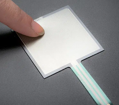
  Force Sensing Resistors (FSRs) represent a critical advancement in sensor technology, offering a versatile and efficient means of measuring force or pressure across a wide range of applications. From consumer electronics to medical devices, automotive systems to robotics, FSRs play a pivotal role in enhancing functionality, safety, and user experience. This article delves into the workings of FSRs, their applications, and the advantages they offer.  What is a Force Sensing Resistor?  A Force Sensing Resistor, also known as a pressure sensor or force-sensitive resistor, is an electronic component whose electrical resistance changes in response to applied force or pressure. Essentially, it’s a thin, flexible, polymer-based material that exhibits a decrease in resistance when pressure is applied to its surface. This change in resistance can be measured and calibrated to determine the magnitude of the applied force.  How do Force Sensing Resistors Work?The fundamental principle behind FSR operation is the conductive polymer material used in its construction. Typically, this material is embedded with conductive particles, and when pressure is applied, the distance between these particles decreases, allowing more current to flow through the sensor. This change in current flow corresponds to a change in resistance, which can be precisely measured.  What’s the applications of Force Sensing Resistors?Human-Machine Interfaces (HMIs): FSRs are extensively used in touch-sensitive interfaces for consumer electronics like smartphones, tablets, and touch-sensitive buttons in appliances. They enable intuitive interaction by detecting the pressure exerted by a user’s touch.  Medical Devices: In medical applications, FSRs are employed in devices such as electronic skin, prosthetics, and pressure-sensitive mats for patient monitoring. They help in measuring pressure distribution for applications like orthopedic rehabilitation or monitoring bedridden patients.  Automotive Systems: FSRs find applications in automotive technologies such as seat occupancy sensors, airbag deployment systems, and touch-sensitive controls in vehicles. They enhance safety by accurately detecting the presence and position of occupants and providing feedback for touch-sensitive controls.  Robotics: FSRs are used in robotics for force feedback systems, grip force sensing in robotic hands, and collision detection. This allows robots to interact safely and accurately with their environment, objects, and humans.  Sports Equipment: FSRs are integrated into sports equipment such as smart insoles, golf club grips, and bicycle handlebars to measure pressure distribution, grip force, and impact forces. This data can be used for performance analysis, injury prevention, and technique improvement.  What’s the advantages of Force Sensing Resistors?Flexibility: FSRs are thin and flexible, making them suitable for applications where space and form factor are constraints.  Low Power Consumption: They typically require low power to operate, making them suitable for battery-powered devices.  High Sensitivity: FSRs exhibit high sensitivity to force or pressure changes, enabling precise measurement across a wide range of forces.  Cost-Effective: Compared to other force sensing technologies like load cells or piezoelectric sensors, FSRs are often more cost-effective, making them a preferred choice for many applications.  Easy Integration: FSRs can be easily integrated into existing electronic systems due to their simple design and compatibility with standard electronic interfaces.  What are the components of Force Sensing Resistors FSR?Force Sensing Resistors (FSRs) typically consist of several components that work together to detect and measure force or pressure. These components include:  Substrate Material: FSRs are usually constructed using a flexible substrate material, often made of polymers like polyethylene or polyvinyl chloride (PVC). This substrate provides the foundation for the sensor and allows it to conform to curved or irregular surfaces.  Conductive Polymer: The key component of an FSR is the conductive polymer layer. This layer is typically applied to the substrate and contains conductive particles dispersed throughout a polymer matrix. When pressure is applied to the sensor, the distance between these particles decreases, leading to a reduction in electrical resistance.  Conductive Traces: FSRs often incorporate conductive traces or electrodes on the substrate, which are used to connect the sensor to external circuitry. These traces provide electrical connections for measuring the resistance of the sensor and transmitting data to a microcontroller or other electronic devices.  Protective Layer: Many FSRs feature a protective layer on top of the conductive polymer to shield it from environmental factors such as moisture, dust, and mechanical damage. This protective layer may be made of materials like silicone rubber or polyimide film.  Connector: In some cases, FSRs may include a connector or terminal for easy integration into electronic systems. This connector allows for quick and secure electrical connections without the need for soldering.
Key word:
Release time:2024-05-29 11:39 reading:1050 Continue reading>>
What are matching <span style='color:red'>resistor</span>s?What are the functions of matching <span style='color:red'>resistor</span>s?
  In the design and manufacturing process of electronic products, PCB (Printed Circuit Board) board design is a crucial link. In PCB board design, the use of matching resistors plays a decisive role.  So, what exactly is a matching resistor? What role does it play in PCB board design? This article will provide an in-depth analysis of the importance and specific role of matching resistors in PCB board design.  What are matching resistors?Matching resistors refer to resistors that have nearly identical electrical characteristics, including resistance values, tolerance, and temperature coefficients. These resistors are specifically chosen and paired to ensure that the electrical properties across different parts of a circuit are as uniform as possible. This matching process is critical in applications where balance, precision, and stability are essential.  What are the functions of matching resistors?  1. Impedance matching  Impedance matching is the most direct and important role of matching resistors. In circuits with high-speed signal transmission, the integrity of the signal largely depends on whether the impedance of the circuit is matched.  If the impedances of the transmitter and receiver do not match, the signal will be reflected during transmission, resulting in signal distortion or even complete loss.  By reasonably setting matching resistors in the circuit, the impedances of the transmitting end and the receiving end can be matched, thereby reducing signal reflection and distortion and ensuring signal integrity and stability.  2. Terminal matching  In addition to impedance matching, matching resistors are also commonly used for termination matching. In long-line transmission or high-speed digital signal transmission, due to the inductance and capacitance effects of the line, the signal may ring at the end of the transmission line.  By connecting a matching resistor in parallel to the ground at the end of the transmission line or connecting a matching resistor to VCC (positive power supply), the reflected signal can be effectively absorbed, the ringing phenomenon eliminated, and the signal transmission quality improved.  3. Voltage division and current limiting  In addition to the above two main matching functions, matching resistors can also play the role of voltage dividing and current limiting in the circuit.  In some situations where precise control of voltage or current is required, precise adjustment and control of voltage or current can be achieved by reasonably setting the resistance of the matching resistor.  In addition, in some situations where sensitive devices need to be protected from excessive current impacts, matching resistors can also be used as current-limiting resistors to protect the circuit.  What’s the application of matching resistors?  ● Amplifier Circuits:  In amplifier circuits, matching resistors are often used in critical stages to maintain balance and symmetry. Balanced resistors help ensure that signals passing through the amplifier are accurately amplified without distortion. This is particularly important in audio applications where fidelity is a key consideration.  ● Voltage Divider Networks:  In voltage divider circuits, matching resistors are employed to divide an input voltage into precise fractions. Any mismatch in resistor values can result in inaccurate voltage division, leading to errors in the output signal. Precision is crucial in applications like sensor networks and measurement devices.  ● Bridge Circuits:  Wheatstone bridge circuits, commonly used in precision measurement applications, rely on the accurate matching of resistors. This ensures that the bridge is balanced, providing accurate and stable readings in applications such as strain gauge sensors and temperature sensors.  ● Feedback Networks:  Matching resistors play a crucial role in feedback networks of operational amplifiers. In circuits employing negative feedback, the resistors are often matched to maintain a stable and predictable gain, contributing to the overall performance and reliability of the amplifier.  Principles for selecting matching resistorsWhen selecting matching resistors, certain principles need to be followed to ensure circuit performance and stability.  First, the resistance of the matching resistor must be determined based on the operating frequency of the circuit and the characteristic impedance of the transmission line. Secondly, the power handling capacity of the matching resistor should be considered to ensure that it will not be damaged due to overheating during operation.  In addition, factors such as the accuracy and stability of the matching resistors need to be considered to ensure that their impact on circuit performance is minimized.
Release time:2024-02-26 16:31 reading:1865 Continue reading>>
What are the advantages and disadvantages of light-dependent <span style='color:red'>resistor</span>s
  What is LDRLight Dependent Resistor (LDR) is a type of sensor used to detect the intensity of light. It is also known as a photoresistor or photocell. It is a passive electronic component, which means that it doesn’t require any power source to operate. Instead, it works by changing its resistance based on the intensity of light that falls on it.  It is a device that changes its resistance based on the amount of light it receives. It is usually made up of two metals or semiconductors, one for the anode and one for the cathode. When no light falls on an LDR, its resistance will be low, and vice versa when there is plenty of light coming down onto it. The change in electrical current between these two metals causes them to repel each other; therefore, if you place your finger over one side’s terminal while holding another wire with its terminal connected to the ground via some sort of switch or button, then all you’ll feel is static electricity!  How many types of LDR are there  There are two types of LDRs – intrinsic and extrinsic.  ◎ Intrinsic LDRs are made of semiconductor materials that exhibit photoconductivity naturally, such as cadmium sulfide (CdS) or lead sulfide (PbS).  ◎ Extrinsic LDRs are made by doping a semiconductor material with impurities, such as arsenic, to enhance its photoconductivity.  What are the advantages and disadvantages of light-dependent resistorsA light-dependent resistor is a device that changes its resistance depending on the amount of light hitting it. LDRs are used in a variety of applications and have many advantages over other types of resistors.  The advantages of LDR include its low cost, simplicity of use, and low power consumption. LDRs are also sensitive to a wide range of light frequencies, making them useful in many applications.  However, LDRs have some disadvantages. They are slow to respond to changes in light intensity and can be affected by temperature changes. Additionally, their resistance can vary significantly between individual components, making it difficult to achieve consistent performance.  What does a Light Dependent Resistor doA light-dependent resistor (LDR) is a resistance that changes its resistance based on the amount of light that falls on it. It is used in various applications like photodiodes, photocells, light sensors, etc. It is also used in photovoltaic applications to convert solar energy into electricity using photocurrent generation.  Where is LDR used  LDR is used in a lot of applications. It is used to measure the intensity of light, detect the presence of light, and detect its intensity in a sensor.  LDRs are used in a wide range of applications, including streetlights, security systems, cameras, and light meters. In streetlights, they are used to turn on the lights when it gets dark and turn them off when it gets light. In security systems, they are used to detect the presence of intruders by sensing changes in light intensity. Cameras use LDRs to control the exposure settings, while light meters use LDRs to measure the intensity of light in a scene.  How do you use LDR in a circuitLDRs can be used in a variety of PCBs , such as voltage dividers, oscillators, and timers. A voltage divider circuit consists of an LDR and a fixed resistor connected in series. The output voltage of the circuit varies based on the resistance of the LDR, which changes with the intensity of light. Oscillator and timer circuits use LDRs to control the frequency or duration of a signal based on the light intensity.  What is the difference between LDR and a photoresistorA light-dependent resistor (LDR) is a special kind of resistor that works based on the amount of light it receives. It has two terminals one terminal goes to the ground, while the other terminal goes to the power. If no voltage is applied, it will be in its lowest resistance state and if you apply a high enough voltage through this pin, it will become active and start flowing electricity through its internal wiring.  LDRs and photo resistors are two different types of sensors used to detect light. LDRs are made of semiconductor materials and change their resistance based on the intensity of light.  Photo resistors, on the other hand, are made of a thin film of a material that changes its conductivity based on the intensity of light. While both sensors can detect light, LDRs are more sensitive and provide a wider range of detection.  What is the construction of an LDRThe device consists of a semiconductor material and an electrode, which can be biased by applying a small electric current through them. When exposed to light, electrons are knocked out of their orbitals around the atoms in this material.  An LDR is typically constructed using a semiconductor material, such as CdS or PbS. The material is sandwiched between two metal electrodes, which form the terminals of the component. The surface of the semiconductor is often treated with a protective layer to prevent damage from dust or moisture.  What material is used in LDR  In LDR, the active material is made of semiconductors. The p-n junction is a key component of this application. A p-n junction has two regions with different electrical conductivities: one region where electrons flow easily and another region where they don’t move so well.  To make an LDR (or any transistor), you need these Materials.  ◎ The most common material used in light-dependent resistors (LDRs) is cadmium sulphide, CdS. This material has a high resistance to light and even higher heat resistance. The resistance of CdS is dependent on the intensity and wavelength of light that it encounters.  ◎ Lead sulphide, PbS is another commonly used material for LDRs. Lead sulphides are semiconductors that have a low band gap and are therefore sensitive to visible light. Lead sulphide has a higher resistance than cadmium sulphides because it does not absorb as much light at longer wavelengths (which is why you can see through it).  ◎ Indium antimonide, InSb, is another material commonly used in LDRs due to its high conductivity for visible light and heat.  What is the resistance of an LDR  An LDR is a light-dependent resistor (LDR) that changes its resistance according to the amount of light falling on it. This can be used to control electrical devices such as LEDs, fluorescent lamps, and laser pointers.  The resistance of an LDR is measured in milliohms (1MΩ) or microohms (µΩ), depending on whether you’re measuring with a high-voltage probe or low-voltage one respectively. The reason for this relates to how electrons behave when they move through materials: they prefer moving from the left side to the right side rather than vice versa due to their charge polarity.
Release time:2023-11-28 10:55 reading:2489 Continue reading>>
What is a wire wound <span style='color:red'>resistor</span>?  How wire wound <span style='color:red'>resistor</span>s are made?
  Wire wound resistors have a pivotal function within contemporary electrical and electronic setups, ensuring the circuit operates optimally by providing exact and managed resistance. Their construction involves encircling a non-conductive core with a resistive wire, typically composed of nichrome or comparable alloys with high resistance.  This method yields resistors that possess precision, steadiness, and the capacity to handle substantial power loads. The significance of these resistors is evident in their broad application across diverse industries, ranging from power electronics to industrial machinery.  This versatile application is due to their capacity to maintain precise resistance values and endure robust power dissipation demands. To fully utilize the advantages, they offer in different electronic systems, it’s essential to grasp the components, materials, and attributes of wire-wound resistors.  What is a wire wound resistor?A resistor composed of wound wire, the wire wound resistor, serves the purpose of imparting a specific resistance value with precision in an electrical circuit. The manufacturing process involves the coiling of a resistive wire, commonly fashioned from materials such as nichrome (nickel-chromium) or comparable alloys, around a core or structure that lacks conductivity. The resistor’s resistance value and additional electrical attributes are contingent upon factors such as the length, diameter, and winding style of the wire.  Through the winding procedure, precise management of the resistance value is achieved, constituting a vital aspect in attaining accurate resistance as needed. The wire wound resistors are recognized for their heightened precision, steadiness, and capability to handle substantial power loads. These qualities render them apt for a wide range of applications, particularly in instances where precision and dependability hold significance. Their frequent application spans across power electronics, industrial machinery, electronic apparatus, and various systems necessitating exact resistance levels and effective power dissipation.  Why are wire wound resistors used?Utilized extensively within the domain of electrical and electronic circuits, wire wound resistors serve pivotal functions. The key benefit they offer is the provision of highly precise and unwavering resistance values. The methodology involves encircling a resistive wire around a core devoid of conductivity, affording meticulous command over resistance—a notable advantage, particularly in cases demanding precise resistance for circuit efficacy.  Furthermore, wire wound resistors adeptly manage substantial power loads, making them optimal for scenarios expecting significant power dispersion. This attribute finds paramount importance in power electronics, industrial machinery, and high-powered systems, where maintaining steady resistance amidst hefty power demands is vital for top-tier performance and safety.  Additionally, wire wound resistors boast longevity and dependability, ensuring a consistent performance throughout extended operational lifecycles, further solidifying their significance across varied electronic applications.  How wire wound resistors are made?Constructed through the coiling of a resistive wire, typically of nichrome or akin materials, around a core or bobbin that insulates, wire wound resistors manifest. The winding process, executed in a particular manner and density, results in the intended resistance value. Characteristics of the resistor, encompassing resistance, tolerance, and ability to handle power, are dictated by factors such as the wire’s properties, diameter, length, and the approach employed for winding.  How does a wire wound resistor work?In the event of an electric current coursing through a wire wound resistor, the resistive wire generates resistance to counter the current flow. This opposition transforms electrical energy into warmth, dispersing it to the surroundings. The extent of the resistance hinges on both the resistivity and the length of the wire.  What is the difference between carbon resistor and wire wound resistor?Manufacture of carbon resistors involves combining carbon with ceramic elements, resulting in a diminished precision and power capacity compared to wire wound resistors. Conversely, wire wound resistors employ a wound wire composed of particular resistive alloys, enabling greater precision and power management potential.  What are the parts of wire wound resistor?  Key components constituting a wire wound resistor encompass:  1.The Resistive Wire: Serving as the nucleus of a wire wound resistor, it furnishes the desired electrical resistance. This wire is usually fashioned from resistive substances such as nichrome (nickel-chromium) or comparable high-resistivity alloys to achieve the target resistance level.  2.The Core or Form: Encompassing a non-conductive material, the resistive wire is entwined around this core or form. This component bestows structural reinforcement and ensures uniform winding of the wire, enabling meticulous regulation of the resistance. Common core materials encompass ceramics, fiberglass, or plastics.  3.End Caps or Terminals: Wire wound resistors house two terminals or end caps, typically comprised of conductive material, facilitating electrical connections to the resistor. The resistive wire links to these terminals, allowing the passage of electrical current throughout the resistor.  Collectively, these constituents shape the foundational framework of a wire wound resistor, enabling its operation by supplying a managed and exact resistance within an electrical circuit.  What material is used for wire wound resistor?  The chief material employed for the resistive portion within a wire wound resistor is a distinct alloy denominated nichrome, a contraction for nickel-chromium. Nichrome gains extensive utilization owing to its elevated resistivity, signifying it can present a considerable level of electrical resistance in a comparatively petite quantity of material. Typically, this alloy consists of a blend of nickel (approximately 80-90%) and chromium (around 10-20%).  The elevated resistivity of nichrome renders it a superb selection for crafting resistors, enabling the attainment of meticulous resistance values based on the wire’s length, diameter, and coiling design. Furthermore, nichrome delivers commendable steadiness at elevated temperatures and sustains its resistive characteristics over an extensive spectrum of operational circumstances, thus rendering it apt for diverse applications, encompassing those involving power dispersion.  Besides nichrome, alternative alloys or materials boasting high resistivity can be utilized; nonetheless, nichrome persists as one of the most prevalent and efficient materials for wire wound resistors, given its appealing electrical and thermal traits.
Key word:
Release time:2023-10-10 13:26 reading:1594 Continue reading>>
What is a thick film <span style='color:red'>resistor</span> Advantages of thick film <span style='color:red'>resistor</span>s
  What is a thick film resistor?  Thick film resistors are electronic components that are thicker and have higher resistance quality than thin-film resistors. They are usually made from a layer of thick film-resistive material (chromium, nickel, etc.) that is screen-printed, baked and sintered on a ceramic substrate.  Thick film resistors have the advantages of wide resistance range and low manufacturing cost. In addition, in high-frequency applications, thick film resistors have better noise characteristics and stability, as well as higher output power. At the same time, thick film resistors also have the characteristics of high temperature, high humidity and high heat resistance, so they are especially widely used in high temperature or harsh environments.  Thick film resistors are mainly used in current limiting, voltage dividing and circuit calibration in electronic circuits. In some advanced applications in recent years, thick film resistors have also been used in very large-scale integrated circuits (VLSI) technology, such as circuit boards and chip components in embedded systems.  Advantages of thick film resistorsThick film resistors have the following advantages over thin film resistors:  1. Wide resistance range: The resistance range of thick film resistors is wider than that of thin film resistors, ranging from a few ohms to hundreds of megohms, and different resistance values can be formulated according to user requirements.  2. High output power: Thick film resistors have higher output power and can withstand larger currents and powers, which makes them more reliable and stable in high-power applications.  3. Low manufacturing cost: Thick film resistors have low manufacturing cost, a simple manufacturing process and high production efficiency, so the product price is more economical than thin film resistors.  4. Strong performance in high temperature, high humidity and heat resistance: Thick film resistors perform better in high temperature, high humidity and heat resistance, and have higher stability in long-term use in harsh environments.  5. Good reliability: Thick film resistors have stable performance, their functions are not easy to change under normal use, and their reliability is higher than that of thin film resistors.  Based on the above advantages, thick film resistors are suitable for fields requiring high output power, wide resistance range, high temperature, high humidity and heat resistance, such as automotive electronics, industry, military, aviation, etc.  What are the applications of thick film resistors?  Thick film resistors are mainly used in current limiting, voltage dividing and circuit calibration in electronic circuits. The following are common application scenarios for thick film resistors:  1. Current limiting and voltage dividing applications: Thick film resistors play the role of adjusting the voltage and current in the circuit. They are mainly used to limit, balance and distribute the size of the current to ensure the stability and reliability of the circuit. For example, electronic components in voltage-controlled oscillators require stable resistance values, and sometimes multiple thick film resistors must be connected in a cascade to form a voltage dividing ratio to achieve the goal.  2. Temperature sensor: Some thick film resistors can be used as temperature sensors to a certain extent because although the resistance value is related to the amount of current, its value is also affected by temperature.  3. Timers and other applications: Thick film resistors are widely used in various electronic equipment such as timers, frequency meters and current measuring instruments. It can also be used in various applications such as filters, dampers, voltage dividers, voltage drops and calibration circuits.  4. Embedded systems: In embedded systems, thick film resistors are also widely used in circuit boards, chip components, etc., and are used in control circuits of various embedded systems, such as IoT devices, sensors, etc.  In general, thick film resistors have a wide range of applications, and their advantages are particularly obvious in practical applications. Their use can effectively improve the performance of electronic circuits and achieve higher stability and reliability requirements.  How to choose thick film resistors?  When purchasing thick film resistors, you need to consider the following factors:  1. Resistance range: Thick film resistors with a wide resistance range can be purchased as needed to select the most suitable resistance value in different application scenarios. Generally speaking, the resistance of thick film resistors ranges from hundreds of ohms to hundreds of megaohms.  2. Resistance accuracy: The appropriate resistance accuracy needs to be selected according to the accuracy requirements of the circuit. Generally speaking, the resistance accuracy of thick film resistors is between ±1% and ±5%.  3. Power: The appropriate power needs to be selected based on the current in the circuit and the power supply voltage. Generally speaking, the power of thick film resistors is between 1/4 watts and 5 watts. The greater the power value, the larger the resistor volume.  4. Temperature coefficient: An appropriate temperature coefficient needs to be selected based on the accuracy requirements of the circuit and the temperature change range in the working environment. Generally speaking, the temperature coefficient of thick film resistors is between ±100ppm/℃ and ±500ppm/℃.  5. Interface type: The appropriate interface type needs to be selected according to the specific application scenario. For example, some are patch type, suitable for SMT process, and some are plug-in type, suitable for DIP process.  6. Other special requirements: such as withstanding driving voltage, current and volume, etc. Some application scenarios and requirements for implementing specific functions also require special attention.  Finally, it is important to note that when purchasing thick film resistors, you need to pay attention to the supplier’s reputation and product quality, purchase products from regular channels, and select appropriate models based on actual needs to ensure that you purchase suitable, reasonably priced, and reliable quality products.
Key word:
Release time:2023-09-18 15:25 reading:2139 Continue reading>>
What is thin-film <span style='color:red'>resistor</span> Difference between thin-film <span style='color:red'>resistor</span>s and thick-film <span style='color:red'>resistor</span>s
  There are many types of resistors. Thin-film resistors are one of the commonly used ones. What are the types of thin-film resistors? What materials are commonly used to make thin-film resistors? In what fields are thin-film resistors mainly used?  What is thin-film resistor?Thin-film resistors are made by evaporating materials with a certain resistivity on the surface of insulating materials using a similar evaporation method. Generally, the insulating material commonly used for this type of resistor is ceramic substrates.  In recent years, with the rapid development of electronic information technology, the development of A/D, D/A conversion circuits and other linear or nonlinear circuits has been rapid. Among them, high-precision operational amplifiers with thin-film resistor networks as the core and high-precision A/D and D/A conversion circuits are essential. In order to improve the accuracy and resolution of ADCs and DACs, the performance of thin-film resistors must also be improved accordingly.  The accuracy and resolution of DAC and ADC mainly depend on the resistor network inside the device. DAC and ADC conversion devices generally use R-2R ladder resistor network. The analysis, research and production of resistor network performance have always been key technologies in the development and production of analog devices. High-precision thin-film resistors have become more and more popular in high-tech fields such as aviation, national defense, electronic computers, communication instruments, and electronic switches due to their excellent characteristics such as high resistivity, low temperature coefficient of resistance, high stability, no parasitic effects, and low noise.  Features of thin-film resistorsTantalum nitride film  Low parasitic capacitance  Good solderability and bonding performance  Temperature coefficient: 150ppm/℃ (-55℃~+125℃)  Rated power 1000mW  Electrode temperature resistance 400℃×10min  Difference between thin-film resistors and thick-film resistorsThin-film Resistors vs Thick-film Resistors  1. Difference in film thickness: The film thickness of thick-film resistors is generally greater than 10 μm, and the film thickness of thin films is less than 10 μm, mostly less than 1 μm;  2. Difference in the manufacturing process: Thick-film resistors generally use a screen printing process, while thin-film resistors use vacuum evaporation, magnetron sputtering and other process methods. The differences in materials and processes between thick-film resistors and thin-film resistors directly lead to differences in performance between the two resistors. Thick-film resistors generally have poor accuracy, with 10%, 5%, and 1% being common accuracy, while thin-film resistors can achieve 0.01% accuracy of one thousandth, 0.1% accuracy of one thousandth, etc. At the same time, the temperature coefficient of thick-film resistors is difficult to control and is generally larger. Similarly, thin-film resistors can achieve a very low temperature coefficient, so that the resistance value changes very little with temperature and the resistance value is stable and reliable. Therefore, thin-film resistors are commonly used in various types of instruments, medical equipment, power supplies, electrical equipment, electronic digital products, etc.  Common thin-film resistors1. Carbon film resistor  Made by depositing crystallized carbon on a ceramic rod skeleton. Carbon film resistors have low cost, stable performance, wide resistance range, and low-temperature coefficient and voltage coefficient. They are currently the most widely used resistors.  2. Metal film resistor  The alloy material is evaporated on the surface of the ceramic rod skeleton using vacuum evaporation. Metal film resistors have higher accuracy, better stability, noise and temperature coefficient correction than carbon film resistors and are widely used in instrumentation and communication equipment.  3. Metal oxide film  A layer of metal oxide is deposited on the insulating rod. Since it is an oxide itself, it is stable at high temperatures, resistant to thermal shock, and has a strong load capacity.  4. Synthetic film resistor  It is obtained by coating a conductive composite suspension on a substrate, so it is also called paint film resistance. Because its conductive layer has a granular structure, it has high noise and low precision. It is mainly used to manufacture high-voltage, high-resistance, and small resistors.
Key word:
Release time:2023-09-18 15:14 reading:2036 Continue reading>>
Too Many Cars, Too Few Resistors

Turn to

/ 1

  • Week of hot material
  • Material in short supply seckilling
model brand Quote
RB751G-40T2R ROHM Semiconductor
MC33074DR2G onsemi
BD71847AMWV-E2 ROHM Semiconductor
CDZVT2R20B ROHM Semiconductor
TL431ACLPR Texas Instruments
model brand To snap up
TPS63050YFFR Texas Instruments
STM32F429IGT6 STMicroelectronics
BU33JA2MNVX-CTL ROHM Semiconductor
ESR03EZPJ151 ROHM Semiconductor
BP3621 ROHM Semiconductor
IPZ40N04S5L4R8ATMA1 Infineon Technologies
Hot labels
ROHM
IC
Averlogic
Intel
Samsung
IoT
AI
Sensor
Chip
About us

Qr code of ameya360 official account

Identify TWO-DIMENSIONAL code, you can pay attention to

AMEYA360 mall (www.ameya360.com) was launched in 2011. Now there are more than 3,500 high-quality suppliers, including 6 million product model data, and more than 1 million component stocks for purchase. Products cover MCU+ memory + power chip +IGBT+MOS tube + op amp + RF Bluetooth + sensor + resistor capacitance inductor + connector and other fields. main business of platform covers spot sales of electronic components, BOM distribution and product supporting materials, providing one-stop purchasing and sales services for our customers.
Please enter the verification code in the image below:

verification code