How to Discharge a Capacitor : A Step-by-Step <span style='color:red'>Guide</span>
  Capacitors are essential components in electronic circuits, storing electrical energy for later use. However, when working with capacitors, it’s crucial to handle them properly to ensure safety and prevent damage. One important aspect of working with capacitors is “How to Discharge a Capacitor”. In this guide, we’ll walk you through the steps to safely discharge a capacitor, why it’s necessary, and the precautions you should take.  What is capacitors?Before diving into the discharge process, it’s helpful to understand what capacitors are and how they function. A capacitor is an electrical component that stores and releases energy in the form of an electric charge. It consists of two conductive plates separated by an insulating material called a dielectric. When a capacitor is charged, it holds a voltage difference between its plates, which can persist even after power is disconnected.  Why Discharge a Capacitor?1. Safety: Capacitors can retain a significant amount of charge even after the power is turned off. Discharging a capacitor is crucial to avoid electric shocks or damage to electronic components.  2. Maintenance and Repair: When servicing electronic devices, discharging capacitors ensures that there are no residual charges that could interfere with repairs or adjustments.  3. Circuit Design: In some cases, you might need to discharge a capacitor to reset or test electronic circuits.  How to discharge a capacitor?1. Safety First: Power Off the Device  – Unplug the Device: Ensure the device or circuit is completely disconnected from the power source. This is the most critical step in preventing electrical shocks.  – Wait for a Safe Period: Even after disconnecting power, give the capacitor some time to self-discharge. However, don’t rely solely on this; always use proper discharge methods.  2. Use Proper Discharge Tools  – Discharge Tool: For high-voltage capacitors, it’s advisable to use a dedicated capacitor discharge tool, which often includes a resistor to safely dissipate the charge.  – Insulated Tools: For lower-voltage capacitors, you can use insulated screwdrivers or pliers.  3. Discharge Process  – Connect the Discharge Tool: If using a discharge tool with a resistor, connect it across the capacitor’s terminals. If using a screwdriver, carefully touch the insulated handle to both terminals, ensuring you don’t touch the metal parts directly.  – Hold for a Few Seconds: Allow the tool to stay in contact with the terminals for several seconds to ensure the capacitor is fully discharged.  4. Verify the Capacitor is Discharged  – Use a Multimeter: To confirm that the capacitor is completely discharged, use a multimeter to check the voltage across the terminals. A reading close to 0 volts indicates that the capacitor is safe to handle.  5. Dispose of or Store Safely  – Handling: Once discharged, handle the capacitor with care. If it’s to be reused, store it in a safe location where it won’t accidentally get recharged or come into contact with conductive materials.  – Disposal: If you need to dispose of the capacitor, follow local electronic waste disposal regulations to ensure environmentally responsible handling.  Precautions  – Never Short the Terminals Directly: Directly shorting the capacitor terminals with a metal object can cause sparks, heat, and potential damage.  – Use Insulated Equipment: Always use tools with proper insulation to avoid accidental electric shocks.  – Handle with Care: Even discharged capacitors can have residual charges. Handle them carefully to avoid any accidental charge buildup.  ConclusionDischarging a capacitor is a straightforward but essential task when working with electronic devices. By following these steps and taking the necessary precautions, you can ensure both your safety and the proper functioning of your electronic components. Always prioritize safety and use the appropriate tools to handle capacitors effectively. With these practices, you’ll be better equipped to handle capacitors in various electronic applications.
Key word:
Release time:2024-09-25 15:20 reading:777 Continue reading>>
Understanding Schottky Diode : A Comprehensive <span style='color:red'>Guide</span>
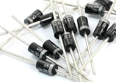
  Schottky diode is semiconductor devices with a unique structure and properties that make it indispensable in various electronic applications. Understanding their principles of operation, advantages, and applications is crucial for engineers and enthusiasts alike. This guide aims to provide a detailed overview of Schottky diodes to help readers grasp their significance in modern electronics.  What is a Schottky diode?A Schottky diode, named after the physicist Walter H. Schottky, is a type of semiconductor diode with a unique construction and operating principle. Schottky diodes are also commonly referred to as Schottky barrier diodes or hot carrier diodes. Unlike conventional p-n junction diodes, which consist of a junction between p-type and n-type semiconductor materials, Schottky diodes are formed by the junction of a metal (often a transition metal like platinum or tungsten) with a semiconductor material (usually silicon).  What is a Schottky diode used for?Schottky diodes find application in a wide range of electronic circuits. They are commonly used in:  Rectification circuits: Schottky diodes are efficient rectifiers due to their low forward voltage drop, making them ideal for converting alternating current (AC) to direct current (DC) in power supplies and voltage regulators.  High-frequency applications: Their fast switching speed and low junction capacitance make Schottky diodes suitable for high-frequency applications such as RF (radio frequency) detectors, mixers, and oscillators.  Protection circuits: Schottky diodes are often employed to protect sensitive electronic components from voltage spikes and reverse polarity damage in circuits such as overvoltage protection and reverse current protection.  What are the advantages and disadvantages of Schottky diode?Advantages:  Low forward voltage drop: Typically around 0.3 V, leading to lower power losses and higher efficiency in rectification applications.  Fast switching speed: Due to their majority carrier conduction mechanism, Schottky diodes have minimal minority carrier storage time, resulting in rapid switching characteristics.  High temperature operation: Schottky diodes can operate at higher temperatures compared to conventional silicon diodes.  Compact size: Their smaller junction area and simpler construction allow for compact designs in integrated circuits.  Disadvantages:  Lower reverse breakdown voltage: Schottky diodes typically have lower reverse breakdown voltage ratings compared to silicon diodes, limiting their use in high-voltage applications.  Higher leakage current: Schottky diodes exhibit higher reverse leakage current compared to silicon diodes, which may be undesirable in certain low-power applications.  Sensitivity to temperature variations: The forward voltage drop of Schottky diodes is sensitive to temperature changes, which can affect their performance in some applications.  What is the difference between Schottky diode and silicon diode?The primary differences between Schottky diodes and silicon diodes lie in their construction, operating principles, and resulting characteristics:  Construction:  Schottky Diode: Schottky diodes are formed by the junction of a metal (usually a transition metal like platinum or tungsten) with a semiconductor material (typically silicon). This metal-semiconductor junction is known as a Schottky barrier.  Silicon Diode: Silicon diodes consist of a junction between two differently doped regions of silicon semiconductor material, forming a p-n junction.  Operating Principle:  Schottky Diode: Schottky diodes conduct current primarily through majority carriers (electrons for n-type semiconductor), resulting in faster switching speeds and lower forward voltage drops. They do not rely on the diffusion of minority carriers for conduction.  Silicon Diode: Silicon diodes conduct current through both majority and minority carriers. In forward bias, majority carriers (holes in the p-type region and electrons in the n-type region) flow across the junction, while in reverse bias, minority carriers (electrons in the p-type region and holes in the n-type region) contribute to the reverse current flow.  Forward Voltage Drop:  Schottky Diode: Schottky diodes typically have a lower forward voltage drop (around 0.3 V) compared to silicon diodes. This is due to the absence of the depletion region present in p-n junction diodes, resulting in lower power losses and higher efficiency in rectification applications.  Silicon Diode: Silicon diodes have a higher forward voltage drop (around 0.6 V to 0.7 V for standard silicon diodes). This is primarily because of the depletion region formed at the p-n junction, which requires a certain voltage to overcome before significant current can flow.  Reverse Breakdown Voltage:  Schottky Diode: Schottky diodes typically have lower reverse breakdown voltage ratings compared to silicon diodes. This limits their use in high-voltage applications.  Silicon Diode: Silicon diodes generally have higher reverse breakdown voltage ratings, making them suitable for high-voltage applications where reverse bias conditions are encountered.  Switching Speed:  Schottky Diode: Due to their majority carrier conduction mechanism and absence of minority carrier storage time, Schottky diodes have minimal switching times, making them suitable for high-frequency applications.  Silicon Diode: Silicon diodes typically have slower switching speeds compared to Schottky diodes due to the presence of minority carrier storage time.  What is the working principle of Schottky diode?  The operation of a Schottky diode is based on the formation of a metal-semiconductor junction, also known as a Schottky barrier. When a metal (such as platinum or tungsten) is brought into contact with a semiconductor material (usually silicon), a potential barrier is formed at the interface due to differences in the work functions of the metal and semiconductor. This barrier prevents majority carriers (electrons in an n-type semiconductor) from easily crossing the junction under reverse bias conditions.  Under forward bias, electrons from the semiconductor flow into the metal, while holes from the metal flow into the semiconductor, resulting in current flow across the junction. Since Schottky diodes do not rely on the diffusion of minority carriers for conduction, they have a lower forward voltage drop and faster switching speed compared to conventional silicon diodes.  How do I identify a Schottky diode?Schottky diodes can be identified by several characteristics:  Forward voltage drop: Schottky diodes typically have a lower forward voltage drop (around 0.3 V) compared to silicon diodes.  Symbol: In circuit diagrams, Schottky diodes are represented by a symbol resembling a regular diode but with a flat line or bar across the cathode end, indicating the metal-semiconductor junction.  Markings: Schottky diodes are often labeled with their part number and may include the letters “SCH” or “SKY” in the part number to indicate their Schottky nature.  Datasheets: Referencing the datasheet of a diode can provide information on its characteristics, including whether it is a Schottky diode.  How do I choose a Schottky diode?When choosing a Schottky diode for a specific application, consider the following factors:  Forward voltage drop: Select a diode with a forward voltage drop suitable for your application requirements to minimize power losses.  Reverse voltage rating: Ensure that the diode’s reverse voltage rating exceeds the maximum reverse voltage expected in your circuit.  Forward current rating: Choose a diode with a forward current rating sufficient for the maximum current expected in your circuit.  Switching speed: Consider the switching speed requirements of your application and choose a diode with a fast enough recovery time.  Temperature range: Verify that the diode can operate within the temperature range of your application.  What is the maximum voltage of a Schottky diode?The maximum voltage (reverse voltage rating) of a Schottky diode varies depending on its specific construction and design. Commonly available Schottky diodes have reverse voltage ratings ranging from a few volts to a few hundred volts. It is essential to consult the datasheet of the diode to determine its maximum voltage rating and ensure it meets the requirements of your application.  Conclusion  Schottky diodes play a vital role in modern electronics, offering advantages such as low forward voltage drop, fast switching speed, and suitability for high-frequency applications. While they have limitations such as lower reverse breakdown voltage and higher leakage current compared to silicon diodes, their unique properties make them indispensable in various circuits. Understanding the principles of operation and key characteristics of Schottky diodes is essential for selecting the right component for specific applications and maximizing their performance in electronic designs.
Key word:
Release time:2024-07-02 13:09 reading:710 Continue reading>>
Ameya360:The A-to-Z <span style='color:red'>Guide</span> on Using Stiffener for Flex and Rigid-flex PCBs
  Lighter electronics with shrinking packages are a reality today mainly due to the emergence of flexible printed circuits (FPC). They are built on materials that can bend smoothly and improve the product’s resistance to vibration and motion. FPCs reduce interconnection defects by minimizing the connection points on the PCB. Their ability to fit in unusual shapes has largely accelerated the miniaturized designs.  With all these advantages, the demand for flex and rigid-flex PCBs has amplified in almost all electronics business sectors. But the material agility makes the flex PCBs susceptible to quick breakdown. A supporting mechanism like a stiffener is hence recommended during the assembly of flex and rigid-flex PCBs to improve the board strength and rigidity.  What stiffeners and why they are needed in flex and figid-flex PCBs  PCB stiffeners are the mechanical parts used during the assembly process to improve the strength of Flex PCBs. They enhance the durability of the PCB by reinforcing the areas in which components will be mounted. Stiffeners add thickness to the board with an impact on cost and manufacturing time in PCB production. Even Rigid-flex PCBs are benefitted from extra strengthening by adding such stiffeners.  They are more often required when the components are in the dynamic areas of the Flex PCBs. Stiffeners are used to avoid stress on the flex boards due to heavy components. There can be pressure on the pads if the connectors require frequent plug-in/plug-out. Stiffeners can hold the PCB surface flat and strong to mount SMT parts efficiently in SMT assembly. They provide the mechanical strength to sustain vibration and shock in harsh operating environments.  Stiffeners facilitate better handling of thin and flexible boards. If there is a requirement for Zero insertion force (ZIF) connectors in the design, they can support the same. Stiffeners improve the bend radius of the PCB and also reduce the stress at flex and rigid circuit junctions. So, they are an integral part of flex and rigid-flex PCBs.  Choose the PCB stiffeners with the right material  Based on the functionality different materials are used to make stiffeners. A PCB busbar is a board stiffener that can conduct electricity. It is made using conductive metals like copper, stainless steel, or aluminum. Non-metal stiffeners are made using polyimide or FR4 material.  FR4 is the common type used for PCB stiffeners in Flex PCB applications. The main purpose of using an FR4 stiffener is to provide the required support for the PCB during the assembly processes like pick-n-place of components and in reflow ovens. They also strengthen the board in areas where connectors and other through-hole parts are mounted. The usual thickness of FR4 stiffeners varies from 0.2mm to 1.5mm. They are more affordable in price compared to other types of stiffeners.  Metal stiffeners like stainless steel or aluminum are highly recommended in applications requiring rigid-flex PCBs to operate in varied temperature ranges. They are a perfect choice in applications demanding corrosion-resistant FPCs. But they are expensive and have a longer bonding process compared to other stiffener materials. Yet, aluminum is ideal for applications involving high thermal dissipation, and stainless-steel stiffeners offer enough support within smaller spaces. While stainless steel stiffeners are available in the thickness range of 0.1mm to 1.5mm, aluminum stiffeners’ thickness can be between 0.2mm to 1.5mm.  Polyimide stiffeners are made from high-temperature polymer sheets in thicknesses ranging from 0.05mm to 0.25mm. They provide exceptional solder resistance and added bond strength. Polyimide stiffeners limit the PCB bending in specific areas while preparing the boards for final assembly. They are best suited to increase the ZIF connector thickness with additional support to contact fingers on the circuit board.  How to mount the stiffeners on flex PCBs  While assembling the stiffeners on a PCB, there are a few key factors to consider. In boards using through-hole parts, it is recommended to position the stiffener on the same side as the components to provide easy access to the solder pads on the PCB. To relieve the stress, there should be around 0.762 mm of overlap of the stiffener on the exposed coverlay of the flex PCBs. If multiple stiffeners are used, then the same stiffener thickness has to be maintained.  To ensure proper alignment, FR4 stiffener holes are enlarged by around 0.3mm as compared to flex board holes. FR4 stiffeners are mounted on the array border to ruggedize the assembly array. This can assist in the automated assembly of flex PCBs similar to rigid PCBs. Also, the need for further tooling plates can be eliminated.  Stiffeners are mounted on the flex PCBs using either pressure-sensitive adhesives or thermally bonded adhesives. Pressure-sensitive adhesives are used in IPC class 2 products while thermally bonded adhesives are preferred in application-critical IPC class 3 products. Thermal bonding adhesives provide strong bonding of stiffeners to the PCB and are expensive. They damage the board significantly if the stiffeners have to be removed. Hence, the application process is quite crucial. On the contrary, pressure-sensitive adhesives are low-cost with medium bond strength. The PCB damages can be avoided with the careful removal of bonded stiffeners while using pressure-sensitive adhesives.  Can stiffeners improve PCB performance?  Using stiffeners in Flex and Rigid-flex PCBs offers several advantages in the overall performance of the product. They provide structural support in fragile areas of flex PCBs and minimize mechanical deformities like bending and warping. Also, they avoid any possible electrical shorts in the stacked PCBs of a chassis.  In harsh environments, stiffeners protect PCBs against pressure and vibration. They can also avoid mounting screws or rivets on PCBs, reducing the cost of such additional fittings. Using busbars can improve the power distribution for the ground circuit of the PCB. They can assist in quick thermal dissipation in high-temperature applications. Thus, stiffeners are remarkable in improving the overall performance and structural integrity of the FPCs.  Conclusion  To control the cost and quality of flexible printed circuits, it is important to work with an experienced contract manufacturer (CM). Building stiffener PCBs with optimized quality and reduced cost is possible if your CM has adopted quality management guidelines and is equipped with the latest technologies in the production line. Further, this comprehensive guide on stiffeners will enable you in understanding the right choice of material, adhesive types, key mounting considerations, and their usage in Flex and Rigid-flex PCBs.
Key word:
Release time:2023-02-16 15:28 reading:2016 Continue reading>>
Nvidia Crushes Fourth-Quarter Sales, Earnings Targets, <span style='color:red'>Guide</span>s Higher
  Graphics-chip maker Nvidia (NVDA) late Thursday smashed Wall Street's estimates for its fiscal fourth quarter and guided higher for the current quarter, sending its stock up sharply in extended trading.  Nvidia reported earnings per share of $1.78, up 80% year over year, on sales of $2.91 billion, up 34%, in the quarter ended Jan. 28. Analysts expected earnings of $1.16 a share on sales of $2.67 billion for the January quarter, according to Zacks Investment Research.  Nvidia shares surged 11% in after-hours trading on the stock market today. During the regular session, Nvidia fell 4.9% to 217.52.  For the current quarter, Nvidia expects revenue of $2.9 billion, up 33% year over year. It did not give a target for earnings per share. Nvidia expects its GAAP gross profit margin to be 62.7% in the first quarter, compared with 61.9% in the fourth quarter.  Wall Street was modeling Nvidia to earn 97 cents a share, up 18%, on sales of $2.44 billion, up 26%, for the April period, according to Zacks.  Nvidia is best known for making graphics processors for PCs and gaming consoles, but has a fast-growing business selling processors for cloud data centers, artificial intelligence applications and self-driving cars. Lately its processors have been used for mining cryptocurrency such as Bitcoin and Ethereum.  IBD'S TAKE: Nvidia is ranked No. 8 on the IBD 50 list of top-performing growth stocks.  "In a powerful sign of our progress, attendees at Nvidia's GPU Technology Conferences reached 22,000, up 10-fold in five years, as software developers working in AI, self-driving cars, and a broad range of other fields continued to discover the acceleration and money-saving benefits of our GPU computing platform," Nvidia Chief Executive Jensen Huang said in a news release.  Huang touted the company's graphics processing units for use in artificial intelligence applications.  "Industries around the world are racing to incorporate AI," he said. "Virtually every internet and cloud service provider has embraced our Volta GPUs. Hundreds of transportation companies are using our Nvidia Drive platform. From manufacturing and health care to smart cities, innovators are using our platform to invent the future."
Key word:
Release time:2018-02-09 00:00 reading:2201 Continue reading>>
3PEAK_Selection <span style='color:red'>Guide</span> ( download only for english page )
Coating eliminates crosstalk and shrinks waveguides
  A way to simultaneously control diverse optical properties of dielectric waveguides by using a quasi 2D two-layer coating has been found by a team of Penn State electrical engineers.  “Waveguides are an essential component in any electromagnetic or optical system,but they are often overlooked because much of the focus has been on the devices themselves and not the waveguides,"said Chair Professor Genevieve McCain.  The researchers developed a material they claim is so thin it is almost 2D,with characteristics that manipulate and enhance properties of the waveguide.  The material is said to be composed of two conformal coatings,one for guiding the signal and one to cloak the waveguide,that were then applied to a rod-shaped,Teflon waveguide.  By engineering the patterning on the coatings'surfaces,the team could control waveguide functionality and the cloaking coating is said to eliminate crosstalk and blockage.  The researchers also claim the effectiveness of the coating can be well maintained for waveguide bends by properly matching the dispersion properties of the metasurface unit cells.Although the coating can be applied to a bend in the waveguide,the waveguide cannot be bent after the coating is applied.  Improving the properties of the waveguide to control polarisation and other attributes is said to allow the waveguides to be smaller,and alleviating crosstalk allows these smaller waveguides to be more closely bundled.  "In terms of applications,these would include millimetre-wave/terahertz/infrared systems for sensing,communications,and imaging that need to manipulate polarisation,squeeze signals through waveguides with a smaller cross-section,and/or require dense deployment of interconnected components,"said postdoctoral fellow Zhi Hao Jiang.
Release time:2017-08-31 00:00 reading:2745 Continue reading>>
Engineer's <span style='color:red'>Guide</span> to Imaging Valley
  Many of us, pleasantly surprised by the new French wave of companies (275, including 233 startups) at the last Consumer Electronics Show, are closely following the vibrant tech startup scene in France.  The grand opening of Station F in Paris in late June, attended by a newly elected French president, is testimony to how France today sees an emerging startup culture as critical to its long-term growth.  Certainly, this boom has exposed countless IoT and wearable startups, who are set up to innovate new software, apps, and services.  Not to be forgotten, though, is that France is a nation known for its hard science.  Military-grade imaging technologies  Over several decades, French researchers and engineers have accumulated a number of key technologies in the field of imaging. They range from X-ray and far infrared to visible image sensors, 3D imaging, and software.  The brain power of France’s military-grade imaging technologies is concentrated in the Grenoble/Lyon area.  Much of France’s knowledge in this area, deeply rooted in defense and military-grade technologies, has been fostered through R&D, technology development, and testing/manufacturing experiences in that region. The French call the Grenoble-Isère area “Imaging Valley.”  Jean-Luc Jaffard, an imaging expert and consultant now serving as Chronocam’s vice president for sensor engineering and operations, called the region “unique.” Within a 25-km radius, “you see concentrations of all the basic imaging technologies — everything from CCD, CMOS, X-ray, and infrared.”  Imaging Valley is as old as Silicon Valley, but lesser-known. The high-tech business in the Grenoble region is much smaller than its U.S. counterpart, its community decidedly insular. The region has spawned few giants such as Intel, Apple, or Google — at least for now.  This is not to say, however, that the region lacks expertise in deep technologies.  Grenoble is home to the renowned European Synchrotron Radiation Facility (ESRF). CEA, the French Alternative Energies and Atomic Energy Commission, opened CEA-Leti in Grenoble 50 years ago. Its mission was focused on the development of microelectronics and information technology.  This is also the region where a lot of French government money has gone to fund scientific research.  As Pierre Cambou, activity leader, Imaging & Sensors at Yole Développement, explained, what started out 50 years ago as technology development for military and nuclear activities switched in the 1980s to semiconductor development. By the 2000s, the region became a center for leading-edge research, tech development, and production of imaging sensors.  The two pillars of Imaging Valley, according to Jaffard, are the military domain and a non-military sector that, together, have developed strains of technologies including CCD, infrared, and CMOS.
Key word:
Release time:2017-08-07 00:00 reading:1241 Continue reading>>

Turn to

/ 1

  • Week of hot material
  • Material in short supply seckilling
model brand Quote
BD71847AMWV-E2 ROHM Semiconductor
MC33074DR2G onsemi
RB751G-40T2R ROHM Semiconductor
TL431ACLPR Texas Instruments
CDZVT2R20B ROHM Semiconductor
model brand To snap up
TPS63050YFFR Texas Instruments
STM32F429IGT6 STMicroelectronics
IPZ40N04S5L4R8ATMA1 Infineon Technologies
ESR03EZPJ151 ROHM Semiconductor
BP3621 ROHM Semiconductor
BU33JA2MNVX-CTL ROHM Semiconductor
Hot labels
ROHM
IC
Averlogic
Intel
Samsung
IoT
AI
Sensor
Chip
About us

Qr code of ameya360 official account

Identify TWO-DIMENSIONAL code, you can pay attention to

AMEYA360 mall (www.ameya360.com) was launched in 2011. Now there are more than 3,500 high-quality suppliers, including 6 million product model data, and more than 1 million component stocks for purchase. Products cover MCU+ memory + power chip +IGBT+MOS tube + op amp + RF Bluetooth + sensor + resistor capacitance inductor + connector and other fields. main business of platform covers spot sales of electronic components, BOM distribution and product supporting materials, providing one-stop purchasing and sales services for our customers.

Please enter the verification code in the image below:

verification code