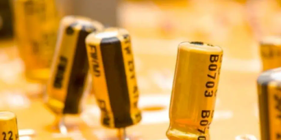
How to select DC-blocking capacitors
  Capacitors are electronic components that are widely used. It is usually used in power filtering, signal coupling, DC blocking and other circuits to improve the stability and reliability of the circuit. The capacitor is widely used in industrial automation, communication equipment, medical equipment and other fields, and is an indispensable part of the electronics industry. In this article, here are some guidelines for you on how to select DC-blocking capacitors.  What is the DC-blocking capacitor?DC -blocking capacitor, also known as coupling capacitor or DC-blocking capacitor, is one of the electronic components that is commonly used in circuits. Its function is to prevent the passage of DC signal and only allow AC signal to pass through.  DC is a signal that has a constant voltage or current, while an AC is a signal that varies in frequency. In some circuits, we want to pass only AC signal and block DC signal. For example, when two circuits are connected together, if the DC component of one circuit is passed to the other circuit, it may cause circuit bias or interference.  By using DC-blocking capacitors, we can block the transmission of DC signal and only allow AC signal to pass through. This is because capacitors have a lower impedance for AC signal (i.e. less voltage drop across the capacitor element across the AC) and higher impedance for DC signals(i.e. less voltage drop across the capacitor element across the DC).  Therefore, DC-blocking capacitors are often used in audio amplifiers, filters, and other circuits that require the isolation of DC. It can help remove bias, reduce noise and interference, and ensure correct transmission of AC.  How to select DC-blocking capacitors?Here are some common tips and considerations when selecting DC-blocking capacitors:  1. Capacitance value selection  The capacitance value determines the impedance of the capacitor to DC signals and the permeability to AC signals. Generally speaking, the capacitance of the DC-blocking capacitor should be large enough to prevent the transmission of DC signals. The specific capacitance selection depends on the requirements of the circuit, usually between a few microfarads (μF) and hundreds of microfarads (μF).  2.Working voltage  Make sure that the working voltage of the selected DC-blocking capacitor is higher than the maximum DC voltage in the circuit. This prevents the capacitor from being damaged due to excessive voltage.  3.Capacitor type  Common types of DC-blocking coupling capacitors include electrolytic capacitors and solid electrolytic capacitors. Electrolytic capacitors have larger capacitance and lower cost, but need to pay attention to polarity. Solid electrolytic capacitors have no polarity requirements, but the capacitance is relatively small.  4.Size and Availability  When selecting a capacitor, also consider its size and availability. Make sure the selected capacitors fit within the board and space constraints and are readily available in the required size and quantity.  5.Temperature and stability  Some applications need to consider the temperature characteristics and stability of the DC-blocking capacitor. In the case of working in a high-temperature environment or being sensitive to temperature changes, choose a capacitor with good temperature characteristics and stability.  It should be noted that the requirements of each circuit may be different, so when selecting a DC-blocking capacitor, it is best to refer to the relevant circuit design guidelines and specification requirements. In addition, since capacitors may age or fail in long-term use, regular inspection and replacement of capacitors is also an important aspect of maintaining circuit performance.  What is the difference between DC-blocking capacitors and bypass capacitors?  DC-blocking capacitors and bypass capacitors are two common capacitor application methods in circuits, and they have some differences. Let’s make a comparison between them.  1.DC-blocking capacitor:  DC-blocking capacitors are mainly used to prevent DC signals from being transmitted through the circuit while allowing AC signals to pass through. It is usually connected between coupling elements in the signal path (such as amplifiers, filters, etc.) to block the effect of DC bias voltage. The capacitance of the DC blocking capacitor is usually chosen to be large enough to pass the required low frequency signal.  2.Bypass capacitor  Bypass capacitors are usually used to bypass certain components or parts of the circuit to provide a short-circuit path for fast bypassing of high-frequency signals. The value of the bypass capacitor is usually chosen to be small enough to provide a low-impedance path for directing high-frequency signals to ground or other reference point. This helps eliminate or reduce noise, interference and oscillations in the circuit.  In general, DC-blocking capacitors are used to prevent the passage of DC signals and allow AC signals to pass through; while bypass capacitors are used to provide short-circuit paths so that high-frequency signals can bypass specific parts of the circuit. They play different roles in circuit design for different signal processing needs.  How to detect whether the capacitor is good or bad?After we have learned something about DC-blocking capacitors, we also need to learn some skills on how to judge whether the capacitor is good or not. Here, we share the usage of a digital multimeter to detect the capacitors.  To check whether the capacitor is good or bad, you can use the resistance file of the digital multimeter. Here are some steps:  1.Plug in your DMM and turn it on, switch it to resistance. The resistance file of the digital multimeter usually has the words “resistance” or “Ω” on the screen. Make sure that the correct resistance range is selected correctly, and select the appropriate range according to the resistance range of the measured resistance.  2. Connect the probes of the digital multimeter to the two pins of the capacitor. Make sure to use the correct pin, otherwise you might get the wrong result.  3. Wait for the digital multimeter to display the resistance reading. If the reading is zero or very close to zero, the capacitor may be damaged or shorted. If the reading is very large or very small, the capacitor may be short circuit or failed.  In some cases, even though there may be no apparent failure of the capacitor, there may still be some underlying problem, such as degraded performance or insufficient stability. In this case, other testing methods can be used to further check the performance and quality of the capacitor. For example, a capacitor tester can be used to test parameters such as the charging and discharging time and resistance value of the capacitor, or an oscilloscope can be used to observe the charging and discharging waveform of the capacitor.  These testing methods may require more advanced equipment and skills, but can provide more comprehensive and accurate test results.  It should be noted that when testing capacitance, safety issues should be paid attention to. Capacitors may store charge, so they should be discharged before testing. A resistor or a capacitor discharger can be used to discharge the capacitor. When testing, you should avoid placing the DMM on metal objects or conductive surfaces to avoid short circuits or other safety issues.
Key word:
Release time:2023-09-01 14:13 reading:2358 Continue reading>>
Which is better ceramic or electrolytic capacitor
  Which is better ceramic or electrolytic capacitor  Ceramic VS electrolytic capacitor  Determining whether ceramic capacitors or electrolytic capacitors are better depends on the specific requirements and characteristics of the application. Each type has its advantages and disadvantages. Here’s a comparison between the two:  Ceramic Capacitors:  • Advantages: Small size, high capacitance in small physical packages, low ESR and ESL, a wide range of voltage ratings, and good temperature stability.  • Disadvantages: Capacitance may be less stable with temperature changes, affected by DC bias voltage, the potential for microphonic noise, and limited capacitance values compared to electrolytic capacitors.  Electrolytic Capacitors:  • Advantages: High capacitance values available, suitable for applications requiring large capacitance, can handle higher voltage ratings, cost-effective, compact size relative to capacitance, suitable for energy storage and filtering.  • Disadvantages: Extremely sensitive poles, limited lifespan compared to some other types of capacitors, voltage and temperature limitations, and reliability issues under certain conditions.  In summary, ceramic capacitors are often preferred because of their small size, low ESR, and high-frequency efficiency, making them suitable for applications such as decoupling, bypassing, and filtering. On the other hand, electrolytic capacitors are beneficial when high capacitance values, energy storage, or cost savings are required in applications such as power supplies, audio equipment and industrial control systems.  Ultimately, the choice between ceramic and electrolytic capacitors depends on specific requirements, operating conditions, and trade-offs that must be considered for a given application.  What is the construction and working of electrolytic capacitorConstruction of an Electrolytic Capacitor:  ● -Anode: The positive terminal is typically made of aluminum.  ● -Cathode: The negative terminal containing a conductive electrolyte.  ●- Dielectric: Thin oxide layer formed on the surface of the anode, acting as the insulating layer.  ● -Electrolyte: Conductive substance filling the capacitor, making contact with the cathode.  Working of an Electrolytic Capacitor:  ●- Polarization: Electrolytic capacitors are polarized, requiring the correct connection of positive and negative terminals.  ● -Electrolyte Charging: Applying a voltage causes electrons to flow from the cathode to the anode through the electrolyte, resulting in charge accumulation.  ● -Electrolyte Layer Formation: An oxide layer forms on the anode’s surface, serving as the dielectric.  ● -Capacitance: The surface area of the anode, dielectric thickness, and electrolyte properties determine the capacitor’s capacitance.  ●- Energy Storage and Discharge: The capacitor stores electrical energy and can release it when connected to a circuit.  It’s important to follow manufacturer guidelines and consider factors such as polarity sensitivity and voltage/temperature limitations for safe and reliable usage of electrolytic capacitors.  How do you know if a capacitor is electrolyticDetermining if a capacitor is electrolytic or not can be done through visual inspection or by checking the labelling or markings on the capacitor itself. Here are some ways to identify an electrolytic capacitor:  ● Physical Appearance: Electrolytic capacitors typically have a cylindrical or can-like shape and are larger compared to other capacitor types.  ● Markings or Labeling: Check for markings or labels on the capacitor indicating its capacitance value, voltage rating, and polarity indicators. Polarity markings (+ and – symbols) suggest that the capacitor is electrolytic.  ● Polarity Indicators: Electrolytic capacitors are polarized and have positive and negative terminals. Look for a longer lead or a plus (+) symbol for the positive terminal and a shorter lead or a minus (-) symbol for the negative terminal.  ● Manufacturer Datasheets or Specifications: The manufacturer’s datasheets or specifications for the capacitor will provides information about its type, including whether it is electrolytic or not.  By considering these factors, you can determine if a capacitor is electrolytic or of a different type.  How do you determine the polarity of an electrolytic capacitor● Physical signs: Check for obvious physical markings on the capacitor, such as a longer cable or symbols (+ and -), indicating the positive and negative terminals, respectively.  ● Labelling: Look for polarity markings or labels on the capacitor’s body or packaging, which may include symbols (+ and -) or words like “positive” and “negative”.  ● Color code: Some electrolytic capacitors have colored bands or stripes on the body, where specific colors represent the anode and cathode.  ● Data sheets or specifications: Refer to the manufacturer’s data sheet or specifications for detailed information on capacitor pin and polarity configurations.  By considering these factors, you can determine the polarity of an electrolytic capacitor. Remember to follow the manufacturer’s guidelines and markings closely to ensure proper polarity connections for safe and reliable operation.
Release time:2023-09-01 13:56 reading:2159 Continue reading>>
​What are electrolytic capacitors ? electrolytic capacitors types
  As a kind of common capacitor, electrolytic capacitors are essential electronic component that is widely used in electronic circuits, power supplies and audio equipment. They have high capacitance value and store and release electrical energy efficiently. This article aims to provide an overview of electrolytic capacitors, their operating principles, common applications, and important considerations when using them.  What is a electrolytic capacitor used forElectrolytic capacitor is a capacitor made of an oxide film formed by electrolysis as a medium. Electrolytic capacitors are used in a wide range of electronic applications due to their specific characteristics and capabilities. Here are some common uses of electrolytic capacitors:  ● Power Supply Filtering  ● Audio Equipment  ● Motor Start and Run Circuits  ● Industrial Control Systems  ● Automotive Electronics  ● Electronic Devices and Appliances  Besides, the specific capacitance, voltage rating and other parameters of electrolytic capacitors may vary depending on the application and requirements of the electronic system. Therefore, choosing the right capacitor type and specification is crucial to ensure optimal performance and longevity in any application.  What are the types of electrolytic capacitors  ■ Aluminum Electrolytic Capacitors:  These capacitors have an aluminum anode, an aluminum oxide dielectric layer, and a conductive electrolyte. They are economical and offer high power values. They can be divided into non-solid aluminum capacitors and solid aluminum capacitors (aluminum polymer capacitors). The non-solid type has a liquid or gel electrolyte, while the solid type uses a solid polymer electrolyte.  ■ Tantalum Electrolytic Capacitors:  Tantalum electrolytic capacitors use tantalum anode, tantalum oxide dielectric and conductive electrolyte. They provide stable capacitance over a wide range of temperatures and frequencies. Tantalum capacitors come in two forms:  solid tantalum electrolytic capacitor, using solid electrolyte and hybrid tantalum electrolytic capacitor, combining tantalum with other capacitor technologies.  Tantalum capacitors can be classified into two subtypes:  ● Solid tantalum Electrolytic capacitor  ● Tantalum hybrid Electrolytic capacitors  Aluminum electrolytic capacitors are commonly used in electrical circuits and audio equipment, while tantalum electrolytic capacitors are commonly found in highly stable applications such as military equipment and medical equipment.  It is important to consider the specific requirements of your application and consult the manufacturer’s instructions to select the correct electrolytic capacitor.  What are the main advantage and disadvantages of an electrolytic capacitorElectrolytic capacitors offer several advantages and disadvantages that are important to consider when selecting and using them.  Advantages:  •-High capacitance values.  •-Compact size.  •-Cost-effective compared to some other high-capacitance capacitor types.  •-Wide range of voltage options available.  Disadvantages:  •-Polarity sensitivity, requiring correct polarity connections.  •-Limited lifespan compared to other capacitor types, requiring periodic inspection and replacement.  •-Voltage and temperature limitations should not be exceeded.  •-Reliability issues, such as electrolyte drying, increased equivalent series resistance (ESR), or leakage under certain conditions.  It is important to consider these advantages and disadvantages in the context of your specific application and requirements. Careful selection, proper handling and following the manufacturer’s instructions are essential to ensure the safe and reliable operation of electrolytic capacitors.
Release time:2023-09-01 13:52 reading:2408 Continue reading>>
RENESAS RX26T new lineup expansion : Suitable for Motor Control Applications
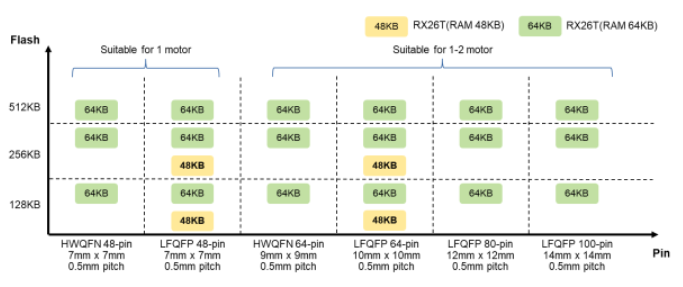
  he RX26T group(The New RX26T – Ideal Microcontroller for Motor Control Applications), is poised to be the natural successor to the RX24T/RX24U. This product, designed especially for dual-motor and PFC control, kicked off its mass production in May 2023.  The RX26T (RAM48KB) variant boasts two package options: 48pin LFQFP and 64pin LFQFP. Additionally, it offers flash memory sizes of 128KB and 256KB.    RX26T Product Lineup  In recent motor/inverter control applications, there's not only a rising demand for IoT compatibility but also a distinct preference among our customers who have favored RX24T for more specialized, high-performance products. These customers look for solutions that can adeptly handle both single motor with PFC control or dual motor control (2 or 3 shunt controls + a 1 shunt control).  Catering to demand, the RX26T (RAM48KB) providing 48 and 64-pin packages retains the best of RX24T – from functional to pin layout compatibility – while introducing enhanced features for complex controls. This includes superior arithmetic capabilities, faster A/D conversion feedback, leading to improved control accuracy and efficiency.  Main improvements include:  Achieve high arithmetic performance with 120MHz operating frequency, the latest RX CPU core RXv3 (721CoreMark), and 120 MHz no-wait Flash access  Equip Trigonometric Function Accelerator essential for motor/inverter control, improving the execution cycle number.  Improve usability and performance of timer and analog functions.  Protects confidential algorithms from leakage and unauthorized copying partially by Trusted Memory.  Support the latest communication standard CAN FD.  Also, when comparing the features of RX24T and RX26T, the table below shows the differences. For more detailed differences, please refer to the application note Differences Between the RX26T Group and the RX24T/RX24U Group that summarizes the differences between the products    Comparison of RX24T and RX26T  Next, let me introduce the evaluation kit.  The RX26T (RAM48KB) product aligns seamlessly with Renesas' latest motor solution platform MCK*1, just like the RX26T (RAM64KB) product. We're also rolling out CPU board MCB*2-RX26T Type C that is equipped with the RX26T (RAM48KB) product. Complementing this, we have prepared motor control sample codes tailored for the RX26T (RAM48KB) product. Simply secure your MCK and MCB-RX26T Type C, download the sample codes from our website, and you're all set for an immediate motor-centric evaluation.  Sensorless Vector Control of a Permanent Magnet Synchronous Motor - For MCK Rev.1.10  Vector Control for Permanent Magnet Synchronous Motor with Encoder - For MCK Rev.1.10  In wrapping up, today's spotlight was on the RX26T group's enriched product. This bolstered lineup is our response to the evolving demands of our customers. As you embark on a new motor control application that commands top-tier performance and features, the RX26T group stands ready as your go-to choice.  *1: Renesas Flexible Motor Control Kit  *2: Renesas Flexible Motor Control CPU Board
Key word:
Release time:2023-08-31 16:52 reading:3291 Continue reading>>
Renesas RZ/G2M Awarded Arm SystemReady IR 1.1 Certification
  Renesas are excited to announce the RZ/G2M-HiHope Reference Board has recently been certified by Arm as a SystemReady IR compliant platform.  What Is Arm System Ready IR?  Arm SystemReady is a set of standards and a compliance certification program that enable interoperability with generic, off-the-shelf operating systems and hypervisors, so that software “just works”. SystemReady comes in a number of domain specific ‘flavors’. The IR variant achieved by the RZ/G2M, verifies it as a futureproof solution for Embedded IoT and Edge sector devices, ensuring true interoperability with embedded Linux and other embedded operating systems, and fast-tracking customer development.  Published details of the Renesas RZ/G2M SystemReady Certification may be found here SystemReady IR – Arm®  SystemReady IR for Renesas RZ/G2M  This SystemReady IR certification completion for Renesas Industrial focused RZ devices, demonstrates a commitment by Renesas to provide software solutions that allow developers to focus on making their products innovative, by reducing the investment needed to bring up a platform ready for Linux. This certification marks the first of many Renesas platforms destined for compliance with the Arm program.  Most embedded software tends to be highly customized. The underlying software and OS are dedicated to a particular platform, and there may often be significant overhead required to make small changes for fixes and/or improvements, or to reflect changes in the underlying hardware. By adapting the existing Renesas RZ software package components to support mandatory open standard interfaces and features, the comprehensive compliance test suite from Arm can ultimately be executed with zero failures. The subsequent clean booting of at least 2 standard OS distribution images “out of the box” confirm the platform’s full compliance.  The RZ/G2M has been verified with Standard Linux distributions from Debian and OpenSUSE, with support for other distributions in the pipeline. By ensuring compatibility and interoperability with the ecosystem, this removes the early end user effort needed to be ready to develop their differentiating software layers on Linux. In addition, it brings with it the further benefits of forming one of the 3 key building blocks of Arm’s Project Cassini, combining with reference applications, and security certification to enable seamless cloud-native deployments to the RZ/G2M.  The Arm SystemReady IR certification of the Renesas RZ/G2M demonstrates a future-focused commitment by Renesas to provide systems that “just work” with the Linux ecosystem, operating systems (OS) and software stacks. In addition, verifying platform requirements for long-term software support and maintenance, ensure that the platform can receive regular updates, bug fixes, and security patches. This ensures that developers have continuous access to a stable and reliable software system.  In short the compliance program helps address both the functionality and increasing complexity, and the real-world concerns in developing platforms with cloud connectivity.  Renesas RZ/G2M Reference Platform  The HiHope RZ/G2M (hihope-rzg2m) is manufactured by Jiangsu HopeRun Software Co., Ltd. and uses the Renesas RZ/G2M SoC. More information about the platform can be found on the HiHope RZ/G2M product page.  The HiHope RZ/G2M platform consists of three parts:  1) Renesas RZ/G2M (r8a774a1) SoC  2) HopeRun HiHope RZ/G2M platform  3) HopeRun expansion board for HiHope RZ/G2 platforms (optional)  Image
Key word:
Release time:2023-08-28 15:38 reading:2955 Continue reading>>
NOVOSENSE capacitive isolation technology to easily solve power challenges
  All electrical products involve power supply, and the common power supply includes voltage regulated power supply, switching power supply, inverter power supply, variable frequency power supply, and uninterruptible power supply. Most power supplies require isolation devices to ensure equipment and personal safety. Because of the different isolation technology used, the isolation effect is also different. Therefore, the choice of isolation products should promote the advantages and avoid the disadvantages, so as to achieve the best system performance as far as possible.  I. Why does the power supply need to be isolated  This is a commonplace problem, and the purpose is to prevent the high voltage of the power supply from endangering the human body. New energy vehicles are a common high-voltage power supply scenario, and the battery voltage is 400V or even 800V; such a high voltage will endanger the human body; another scenario is charging pile, which converts alternating current into high-voltage direct current, and also needs to isolate high and low voltages, which requires the use of isolation devices.  In addition, power supplies in such applications as photovoltaic, data center server, industrial frequency conversion servo, industrial power modules or energy storage devices require measures taken to avoid the harm of high voltage to the human body, in addition to meeting the corresponding safety requirements.    II. Isolation requirements and classification  The isolation is subject to strict safety certification, including such common ones as the US’s UL certification, Germany’s VDE certification and IEC certification of the International Electrical Commission. Safety certification includes two types, one is the system level, such as IEC60065, IEC60950, etc., and the other is the device level, such as UL1577 and IEC60747 standards. The IEC standard defines three levels of energy sources from the perspective of safety, all of which are based on the intensity of voltage and current, and the corresponding protection measures are implemented. It is worth mentioning that all of NOVOSENSE's isolation products have passed UL, CUL, VDE and CQC safety certification.  The isolation chip is widely used in the power system, for example, in vehicle’s OBC/DC-DC system, the input side of high-voltage battery charging is 220V to 380V, and the output side is 400V or 800V; it is 12V to 48V for low-voltage battery charging, which includes PFC and LLC two-stage topologies. The whole system topology is complex, often using two MCUs as the main control, and the communication between the two MCUs needs to be isolated. In addition, the power devices in these topologies, whether Silicon-based MOSFETs or third-generation semiconductor devices, need to be driven and isolated accordingly.  In addition, according to the control accuracy requirements of the system, the functions of voltage sensing, current sensing and external communication of the system also need to be isolated.  III. Several common isolation techniques and requirements  At present, there are three isolation technologies used in the industry: traditional optocoupling, magnetic coupling and capacitive coupling technologies. Traditional optocoupling technology is the most widely used and has the longest history. It uses light as the medium to couple the input signal to the output end, but the volume of the device is large, the transmission speed is slow, the light decay will occur with the growth of the use time, and the operating temperature range is narrow. Magnetic coupling and capacitive coupling are the mainstream isolation technologies. The magnetic coupling has high voltage resistance, fast transmission speed and wide temperature range, but the process is complex with EMI radiation. Capacitive coupling technology has high voltage resistance, fast transmission speed, transmission delay of only twenty or thirty nanoseconds, and a very wide operating temperature range, and the process is not complicated, with high reliability.  NOVOSENSE's isolation chip is based on capacitive coupling technology, using its patented Adaptive OOK® coding technology, with low EMI radiation and low bit error rate, which can effectively improve the isolation device's ability of common‐mode transient immunity (CMTI).  Important indicators of isolation products include: isolation voltage rating, CMTI capability, EMC performance, transmission delay and operating temperature, isolation life, etc. The isolation voltage level of NOVOSENSE’s isolation products is up to 10kV, with CMTI of at least 100kV/μs, anti-surge capability of over 10kV, and bilateral ESD capability of over 15kV.  IV. Power supply system trends and application challenges  (1) Power system trends  -High integration: Power systems are moving towards higher integration, so more integrated ICs are also required, such as integrating power supplies and digital isolators together to reduce the complexity of designing isolated power supplies by engineers.  -High voltage and high frequency: The photovoltaic system has been transferred from 800V to 1500V, the third generation of semiconductors (GaN or SiC) is applied more and more widely, the system switching frequency is getting higher, and the speed is getting faster. Isolation products need to have higher CMTI capabilities, withstand higher voltages, and have better EMI performance.  -High reliability: Isolation chips need to pass strict safety certification.  (2) The application challenges of the power supply system  The application challenge of power system is that the third-generation power device puts forward higher requirements for the driver chip, such as CMTI of greater than 100kV/μs. Due to the higher drive voltage of SiC, the driver output voltage range is required to swing wider. In addition, the product switching rate is faster, and the switching loss is reduced, the driver has the ability to output greater Source or Sink current, the internal rise or fall time is shorter, and the transmission delay is shorter.  The new function of the SiC driver chip is "Miller clamp". with the SiC switching, the middle point of the bridge arm has a large dv/dt, the low side Cgd capacitor will generate a Miller current; even if the low side is in the OFF state, it will also generate a voltage drop through the low side Rgoff . Considering that the on-threshold of the SiC device is relatively low (about 2V), if the voltage drop is large, the low side will be mistaken turn-on of the low side SiC power transistor, and the system will have the risk of short circuit.  The "Miller clamp" function addresses this problem in SiC applications. Adding a MOSFET to the chip can directly connect GND to the SiC grid. After the low side is turned off, the low side driver resistance will be skipped and the grid will be directly short-circuited to GND to eliminate the voltage difference caused by Miller current, thus avoiding the risk of mis-connection of the low side caused by Miller effect.  V. NOVOSENSE isolation products  NOVOSENSE has a wide range of isolation products, including digital isolators, isolated drivers, isolated voltage/current amplifiers, isolated CAN transceivers. In terms of drivers, whether it is MOS, IGBT or SiC, NOVOSENSE has corresponding isolation products. In terms of sampling, it has both analog output isolated operational amplifier and digital output isolated ADC, which can meet the requirements of sampling rate and sampling accuracy in different application scenarios. In terms of interfaces, NOVOSENSE has a wealth of isolated I2C interfaces, and RS485 or CAN interface products, which can provide a one-stop solution for customers' power supply design.  Click the link below to view the corresponding technical articles of the product:  1. Isolated single channel driver with Miller clamp function NSi6601M  2. 5A dual-channel non-isolated driver NSD1624  3. Isolated voltage amplifier NSI1312  The products of NOVOSENSE adopt capacitive coupling technology, which conforms to the current application trend of integrated, high-voltage and reliable power supply, and meets the higher requirements of the third-generation power devices for driver chips. Its isolation product range is very complete, including digital isolators, isolation drivers, isolation voltage/current amplifier, isolated CAN transceivers, providing engineers with a variety of options.
Key word:
Release time:2023-08-25 16:12 reading:4004 Continue reading>>
What are the functions and applications of communication PCB
  Functions of of communication PCB  Communication PCB (Printed Circuit Board) is a basic component for connecting and installing electronic components and is widely used in communication equipment, electronic products, computers and other fields. Its functions and uses mainly include the following aspects:  1. Connection and layout of electronic components  The communication board PCB connects various electronic components together through structures such as wires, pads, and jacks to realize circuit access and signal transmission. It enables tight bonding between electronic components, reducing signal interference and increased resistance caused by air gaps between materials.  2. Installation and fixing of electronic components  The electronic components on the communication board PCB can be installed by welding, inserting, pressing, etc. to ensure the stability and fixity of the electronic components. The pads and sockets on the board can provide reliable contact and connection, and prevent electronic components from falling off due to vibration and physical friction.  3.Circuit reliability and stability  The communication board PCB can improve the reliability and stability of the circuit through wiring planning and interlayer wiring design. It can reduce the distance and line length between circuit components, reduce circuit impedance and signal transmission delay, and improve signal transmission rate and quality.  Applications of communication PCB  Communication equipment  The communication board PCB is the core component of communication equipment, such as mobile communication base stations, wireless routers, optical fiber communication equipment, etc. It can realize information transmission and data exchange between communication devices and ensure the stability and reliability of communication.  Electronic products  Communication board PCB is widely used in various electronic products, such as mobile phones, TVs, computers, etc. It can assemble and wire various components to realize circuit control and signal transmission, which is the basis for the normal operation of electronic products.  Computer  The communication board PCB is also an important part of the computer system, such as the motherboard, graphics card, memory stick, etc. It can connect various hardware devices, realize computer computing and data transmission, and provide a stable working environment for computers.  In the electronic field, the communication board PCB has the functions of connecting electronic components, laying out circuits, fixing components, improving circuit reliability and stability, etc., and is widely used in communication equipment, electronic products, computers and other fields.
Key word:
Release time:2023-08-24 14:58 reading:2571 Continue reading>>
What is the difference between automotive PCB and communication PCB
  Automotive PCBs and communication PCBs are two common types of circuit boards in the electronics industry. Although they look similar on the surface, there are actually certain differences in design, use, and performance. Automotive PCB boards are mainly used in automotive electronic products, which have the characteristics of anti-vibration and high-temperature resistance, and are suitable for harsh automotive environments; while communication PCB boards are mainly used in communication equipment, pursuing high-speed, high-frequency and other characteristics to meet different communication needs.  This article will introduce the differences between these two PCBs in detail to help readers better understand their differences.  Features and applications of automotive PCB boards1.1 Features of automotive PCB boards  The automotive PCB board has the characteristics of anti-vibration, high-temperature resistance, and corrosion resistance to adapt to the harsh environment in which the car is located; its material and manufacturing process requirements are higher to ensure the stability and reliability of the circuit board.  1.2 Applications of automotive PCB boards  Automotive PCB boards are widely used in automotive electronic products, such as car audio, navigation systems, electric vehicle charging piles, etc., to meet the functional requirements of vehicle control, infotainment, and safety monitoring.  Features and applications of communication PCB boards2.1 Features of communication PCB boards  The communication board pursues high-speed, high-frequency and other characteristics, and has the characteristics of high-speed signal transmission and strong anti-interference ability to ensure the stability and reliability of communication equipment.  2.2 Applications of communication PCB boards  Communication boards are widely used in communication equipment, network equipment and other fields, such as mobile phones, routers, base stations, etc., to meet the needs of information transmission and communication.  Difference between automotive PCB and communication PCB  3.1 Material differences  Automotive PCB boards often use materials with high-temperature resistance and compressive strength, such as FR-4 materials; while communication PCB boards often use high-frequency and high-capacity materials, such as PTFE materials.  3.2 Design differences  Automotive PCB boards need to consider the characteristics of anti-vibration and high-temperature resistance, and the design is more stable and strong; while communication PCB boards need to consider high-speed signal transmission and anti-interference capabilities, and the design pays more attention to signal integrity and anti-interference.  3.3 Differences in application environments  Automotive PCB boards are used in the automotive environment and need to be able to adapt to the harsh working environment of the car, such as high temperature, high humidity, vibration, etc.; while communication boards are used in communication equipment, they need to meet the requirements of high-speed transmission and stability.  3.4 Differences in usage  Automotive PCB boards are mainly used in automotive electronic products to meet functional requirements such as vehicle control and infotainment; communication PCB boards are mainly used in communication equipment to meet data transmission and communication needs.  There are obvious differences between automotive PCB boards and communication PCB boards in four aspects: material, design, application environment and purpose. The automotive PCB board is mainly adapted to the harsh working environment of the car, and has the characteristics of anti-vibration and high-temperature resistance; the communication PCB board is mainly used for communication equipment and pursues high-speed, high-frequency and other characteristics. Understanding the characteristics and applications of these two boards will help you choose the right board to meet specific needs in practical applications.
Key word:
Release time:2023-08-24 14:55 reading:2231 Continue reading>>
NXP Semiconductors TJA1051 High-Speed <span style='color:red'>CA</span>N Transceivers
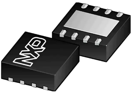
  NXP Semiconductors TJA1051 High-Speed CAN Transceivers offer an interface between a Controller Area Network (CAN) protocol controller and the physical two-wire CAN bus. The TJA1051 is intended for high-speed CAN applications in the automotive industry. The device provides differential transmit and receive capability to (a microcontroller with) a CAN protocol controller.The TJA1051 Transceivers are part of the third generation of high-speed CAN transceivers from NXP Semiconductors, supplying significant improvements over first- and second-generation devices such as the TJA1050. The TJA1051 also provides improved ElectroMagnetic Compatibility (EMC) and ElectroStatic Discharge (ESD) performance with:  • Ideal passive behavior to the CAN bus when the supply voltage is off  • TJA1051T/3 and TJA1051TK/3 can be interfaced directly to microcontrollers with supply voltages from 3V to 5V  The TJA1051 implements the CAN physical layer defined in ISO 11898-2:2016 and SAE J2284-1 to SAE J2284-5. This implementation allows reliable communication in the CAN FD fast phase at data rates up to 5Mbit/s. These features make the TJA1051 an exceptional choice for all types of HS-CAN networks in nodes that do not require a standby mode with wake-up capability through the bus.  The TJA1051 is a high-speed CAN stand-alone transceiver with Silent mode and available in three versions, determined only by the function of pin 5:  • The TJA1051T is backward compatible with the TJA1050  • The TJA1051T/3 and TJA1051TK/3 allow for direct interfacing to microcontrollers with supply voltages down to 3V  • The TJA1051T/E allows the transceiver to be switched to a very low-current Off modeFEATURES  General  ISO 11898-2:2016 and SAE J2284-1 to SAE J2284-5 compliant  Timing guaranteed for data rates up to 5Mbit/s in the CAN FD fast phase  Suitable for 12V and 24V systems  Low ElectroMagnetic Emission (EME) and high Electromagnetic Immunity (EMI)  VIO input on TJA1051T/3 and TJA1051TK/3 allows for direct interfacing with 3V to 5V microcontrollers (available in SO8 and very small HVSON8 packages, respectively)  EN input on TJA1051T/E allows the microcontroller to switch the transceiver to a very low-current Off mode  Available in SO8 package or leadless HVSON8 package (3.0mm x 3.0mm) with improved Automated Optical Inspection (AOI) capability  Dark green product (halogen-free and Restriction of Hazardous Substances (RoHS) compliant)  AEC-Q100 qualified  Low-power management  Functional behavior predictable under all supply conditions  Transceiver disengages from the bus when not powered up (zero loads)  Protection  High ElectroStatic Discharge (ESD) handling capability on the bus pins  Bus pins protected against transients in automotive environments  Transmit Data (TXD) dominant time-out function  Undervoltage detection on pins VCC and VIO  Thermally protected  SPECIFICATIONS  4.5V to 5.5V supply voltage  -8kV to +8kV electrostatic discharge voltage  Supply current  2.5mA silent mode  10mA normal mode, bus recessive  70mA normal mode, bus dominant
Key word:
Release time:2023-08-22 13:23 reading:2179 Continue reading>>
Fibocom 5G R16-compliant Module FM160-EAU Achieved Telstra Certification
  Recently, Fibocom has achieved certification from Telstra, the leading mobile network service provider in Australia, with its SDX62-empowered module FM160-EAU tested on Telstra's 5G network, further verifying the capability of delivering superior and reliable connectivity service to local users.  Shenzhen, China – August 3rd 2023 – Fibocom (Stock code: 300638), a global leading provider of IoT (Internet of Things) wireless solutions and wireless communication modules, announced that the 3GPP Release 16 compliant module FM160-EAU has achieved the Telstra certification. The module has been tested and verified on Telstra's network to provide ahigh-performance 5G broadband service, driving the 5G adoption across industries such as FWA, security monitoring, and Industrial IoT in the regional market.  Broadband demand for regional and remote areas of Australian users has been growing rapidly, and FWA service is expected to cover more than 120,000 homes and business units by the end of 2024, according to Australia's national broadband network (NBN). Meanwhile, 5G is empowered with extended capabilities as 3GPP standard evolves, therefore, it is crucial for FWA service providers to keep up with these advancements and bring an elevated experience for end users. The 5G Sub-6GHz module FM160-EAU is designed to provide an optimal 5G user experience with enhanced coverage, boosted throughput, and increased bandwidth. It is the ideal wireless solution for FWA service providers to bridge the gap of the digital divide by enabling gigabit connectivity for end devices such as CPE, ODU, mobile hot spot, USB dongles, etc.  Based on the Qualcomm Snapdragon® X62 modem chipset, FM160-EAU supports NR CA (Carrier Aggregation), and delivers ultra-fast speed of up to 3.5Gbps DL and 900Mbps UL, significantly optimizing the speed performance for those IoT applications that require high data throughput. In addition to hardware design, FM160-EAU packages in M.2 form factor and pin-compatible with Fibocom's Release15 module FM150, ensuring the smooth migration to advanced generations and minimizing the investment concerns. It is worth highlighting that FM160-EAU is capable of providing high-precision locating service with its built-in GNSS, and allows feasible customization on abundant functionalities such as digital audio, and industry-standard interfaces for the utilization of 5G applications.  "Validating the interoperability tests on Telstra's mobile network and receiving the certification successfully signifies another breakthrough of Fibocom's 5G strategy in the global market," said Gene Santana, VP of Overseas Carriers Certification Department, Fibocom. "With the implementation of 5G infrastructure in the regional market, we hope to deliver the resilient, fast and secure FM160-enabled 5G FWA solution to the Australian market in collaboration with Telstra."
Key word:
Release time:2023-08-22 11:49 reading:3094 Continue reading>>

Turn to

/ 38

  • Week of hot material
  • Material in short supply seckilling
model brand Quote
TL431ACLPR Texas Instruments
MC33074DR2G onsemi
CDZVT2R20B ROHM Semiconductor
RB751G-40T2R ROHM Semiconductor
BD71847AMWV-E2 ROHM Semiconductor
model brand To snap up
IPZ40N04S5L4R8ATMA1 Infineon Technologies
TPS63050YFFR Texas Instruments
BP3621 ROHM Semiconductor
STM32F429IGT6 STMicroelectronics
ESR03EZPJ151 ROHM Semiconductor
BU33JA2MNVX-CTL ROHM Semiconductor
Hot labels
ROHM
IC
Averlogic
Intel
Samsung
IoT
AI
Sensor
Chip
About us

Qr code of ameya360 official account

Identify TWO-DIMENSIONAL code, you can pay attention to

AMEYA360 mall (www.ameya360.com) was launched in 2011. Now there are more than 3,500 high-quality suppliers, including 6 million product model data, and more than 1 million component stocks for purchase. Products cover MCU+ memory + power chip +IGBT+MOS tube + op amp + RF Bluetooth + sensor + resistor capacitance inductor + connector and other fields. main business of platform covers spot sales of electronic components, BOM distribution and product supporting materials, providing one-stop purchasing and sales services for our customers.
Please enter the verification code in the image below:

verification code