NOVOSENSE's isolated driver with protection function helps enhance the safety and stability of the electronic control system in the new energy vehicle

Release time:2024-02-29
author:AMEYA360
source:NOVOSENSE
reading:3440

  The main drive electronic control system is an important part of a new energy vehicle. This article will start from the system block diagram of the electronic control system, introduce the components of the system and their functions, and focus on the use of NOVOSENSE's single-channel isolated driver with protection function NSI6611, in the electronic control system: its Miller clamp function can well prevent short circuits; and the DESAT function can shut down IGBT / SiC in time when a short circuit occurs, protecting IGBT / SiC from damage and ensuring safe and stable operation of the system.

  Contents

  1)Introduction to the main drive electronic control system driver and the NSI6611-based driver board

  1. Composition of the main drive electronic control system

  2. Main chips on the driver board

  3. Interface definition

  4. NSI6611 application circuit

  2)Introduction to Miller clamp and the active Miller clamp function of NSI6611

  1. Miller effect

  2. Active Miller clamp

  3. Short circuit detection of power devices

  3)Introduction to the DESAT protection function of NSI6611

  1. DESAT detection peripheral circuit configuration and parameters

  2. DESAT protection timing

  3. Soft turn-off function

  1) Introduction to the main drive electronic control system driver and the NSI6611-based driver board

  1.1 Composition of the main drive electronic control system

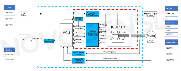
  The main drive electric control system consists of low voltage battery, VCU, MCU, high voltage battery and resolver three-phase motor. As shown in Figure 1 below, inside the blue dotted line is the main drive motor controller part and inside the red dotted line is the driver board that will be highlighted in this article.

  Functionally, the low voltage battery provides low voltage power supply for the system, and the VCU sends instructions to the electronic control system via the CAN bus and reads the status of the electronic control system; the high voltage battery provides high voltage power supply, and the Flyback circuit provides positive and negative voltages for the IGBT driver to drive the three-phase motor; the LDO (low dropout linear regulator) provides +5V power supply for the driver chip. NOVOSENSE's high voltage isolated driver NSI6611 is used to drive the IGBT and SiC modules; the current sampling circuit and resolver-to-digital converter are used to control motor operation.
NOVOSENSE's isolated driver with protection function helps enhance the safety and stability of the electronic control system in the new energy vehicle

  In the main drive electronic control system, NOVOSENSE provides a variety of chips, including the CAN interface chip, resolver-to-digital converter, power supply chip and high voltage isolated driver chip.

  1.2 Main chips on the driver board

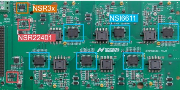
  Figure 2 below is a three-phase drive circuit board designed based on NOVOSENSE's single-channel smart isolated driver NSI6611. The six chips in the blue boxes are all NSI6611. The driver board also uses NOVOSENSE's Flyback power control chip NSR22401 to provide positive and negative voltages for the high voltage drive side of NSI6611; the LDO chip NSR3x provides 5V power supply for the low voltage side of NSI6611.
NOVOSENSE's isolated driver with protection function helps enhance the safety and stability of the electronic control system in the new energy vehicle

  NSI6611 is an automotive-grade, high voltage isolated gate driver with protection function that can drive IGBTs and SiCs, and it supports a peak voltage of up to 2121V and a maximum drive current of 10A without the need for an external drive circuit; CMTI (common-mode transient immunity) can be as high as 150kV/μs. In addition, it integrates active Miller clamp and DESAT (desaturation) protection, soft turn-off and ASC (active short circuit) functions internally, with an operating temperature range of -40°C to +125°C.

  1.3 Interface definition

  As shown in Figure 3 below, the left side of the driver board is the signal interface between the driver board and the control board, including 6 input signals provided by the control board for PWM control; 6 FAULT output signals provided to the control board when NSI6611 detects IGBT overcurrent or undervoltage; 6 Ready output signals used to indicate whether the NSI6611 power supply is undervoltage; and 2 RESET input signals that control 3 high sides and 3 low sides respectively. The right side of the driver board is the power interface, and the power supply voltage range is 9V to 16V.

  1.4 NSI6611 Application Circuit

  Figure 4 below is the drive circuit of NSI6611. The left side is the low voltage control side. The 100Ω resistor connected in series on the signal line can effectively reduce signal reflection; since the Fault and Ready signals have an internal Open Drain structure, a 5.1kΩ pull-up resistor needs to be added. In addition, the RC circuit composed of the PWM signal and a 1nF capacitor can filter out high-frequency signals, and a 0.1μF decoupling capacitor is added to VCC1.

  The right side is the high voltage drive side. Two 1206 package gate resistors are connected in parallel. The gate has a 10k pull-down resistor. The gate capacitance can be adjusted for different applications. The CLAMP pin is connected to the GATE through a 0Ω resistor.

  2) Introduction to Miller clamp and the active Miller clamp function of NSI6611

  2.1 Miller effect

  The Miller effect refers to the phenomenon in a transistor or field effect tube that the capacitance at the output of the amplifier increases due to the interaction between the input capacitance and the gain of the amplifier. It can not only increase switching delay, but also cause parasitic turn-on.

  Due to the inherent characteristics of semiconductors, there are various parasitic capacitances inside the IGBT. The capacitance between the gate and collector is called Miller capacitance. It is often seen in tests that the gate voltage does not rise directly to the VCC voltage, but rises to a voltage plateau, maintains for a period of time and then rises again. This voltage plateau is the Miller plateau, which is generated by Miller capacitance.

  Miller capacitance may also cause false turn-on of the low side. Typically, motor drives require the use of the high and low sides. When Q2 is turned off and Q1 is turned on, a certain current will be generated due to the high dv/dt and Miller capacitance. We can calculate the current by using the formula I=C * dv/dt. The current flowing through the gate resistor will generate a VGE voltage. When this voltage exceeds the turn-on threshold of Q2, Q2 will turn on, and at this time, Q1 is already in the ON state, thus causing a shoot-through short circuit.

  2.2 Active Miller clamp

  In order to solve the problem of shoot-through caused by the Miller effect, negative voltage turn-off can be used, but this will increase the complexity of the power supply design and increase the BOM cost; the second option is to use a driver chip with Miller clamp function to control the IGBT turn-off process.

  The IGBT turn-off process controlled by a driver chip with Miller clamp function is shown in Figure 6 below. First, the OUTL pin is turned on, causing the gate voltage to drop; when the gate voltage drops below the CLAMP threshold, the CALMP pin is turned on, causing the OULT pin to turn off. The resulting path can effectively bypass the gate resistor, thus avoiding the phenomenon of shoot-through. It is worth noting that the Miller clamp module only works when the IGBT is turned off.

  2.3 Short circuit detection of power devices

  IGBT and SiC devices vary in their short circuit capabilities. Before using a power device to design a drive system, you must first understand its basic parameters such as maximum voltage, maximum current and Rdson (on-resistance). Short-circuit capability is also a parameter worthy of focus, since the short circuit characteristics of the device need to be known when short circuit protection is designed.

  Take the short circuit characteristic parameters of the IGBT as an example. At 25°C, its maximum short circuit time is 6μs, which means that the IGBT needs to be turned off in time within 6μs. When the short circuit current reaches 4800A, the value is already several times the normal operating current. Once a short circuit occurs, a large amount of heat will be generated instantly, causing the junction temperature to rise sharply. If it is not turned off in time, the device will be burned and there is even a risk of fire. This must be avoided in system design.

  Generally, the short circuit time of IGBT can reach up to 10μs, while the short circuit time of SiC is only 2~3μs, which brings great challenges to short circuit protection. Therefore, short circuit must be detected and turn-off must be performed in time.

  Method 1 is current detection. A resistor is connected in series with the IGBT, or a current sensor is used to directly detect the overcurrent condition. However, this will increase the cost significantly and make the circuit system more complex.

  Method 2 is desaturation detection, also known as DESAT protection. As shown in Figure 7 below, we can see from the graph of VCE voltage and collector current that when VCE is less than 0.4V, no current flows through the cut-off region; as the VCE voltage increases, the current also increases and a saturation region appears, and then it enters the linear region, i.e., the desaturation region.

  Usually, when the IGBT works in the saturation region, it will enter the desaturation region once a short circuit occurs. It can be seen that the VCE voltage generally does not exceed 2V in the saturation region; if it enters the desaturation region, VCE will rise rapidly and even reach the system voltage. Desaturation detection is to detect whether the IGBT has entered the desaturation region by detecting the VCE voltage.

  3) Introduction to the DESAT protection function of NSI6611

  3.1 DESAT detection peripheral circuit configuration and parameters

  DESAT detection consists of NSI6611 and external DESAT capacitor, resistor and high voltage diode. The NSI6611 chip integrates a 500μA constant current source and comparator internally.

  When the IGBT is turned on normally, the VCE voltage is very low, basically below 2V, and the diode is in a forward turn-on state. The voltage value of VDESAT is equal to the voltage drop of the resistor plus the voltage drop of the diode, plus the VCE voltage. Assuming that the resistance of the resistor is 100Ω, the forward voltage drop of the diode is 1.3V, and VCE is 2V, then, according to the formula in Figure 8, we can get: When the IGBT is turned on normally, the voltage detected by DESAT is basically less than 3.35V.

  When the IGBT is short-circuited, the VCE voltage will rise rapidly. At this time, the diode is in the OFF state, and the current will flow to the DESAT capacitor and charge it. Since the DESAT current of NSI6611 is 500μA and the DESAT threshold is 9V, this means that a capacitor needs to be matched to charge the DESAT capacitor to 9V at 500μA within the short circuit time.

  Assuming that the DESAT capacitance is 56pF, according to the capacitor charging formula in Figure 8: the charging time of the capacitor is about 1μs; plus the blanking time of 200ns and the filtering time of 200ns, the total short circuit protection response time is 1.4μs. This time is not only shorter than the safe short circuit time of IGBT, but also shorter than the safe short circuit time of SiC.

  3.2 DESAT protection timing

  Figure 9 below is the DESAT protection timing diagram. It can be seen from the figure that in step 1, GATE rises and DESAT starts the blanking time; in step 2, the blanking time ends and the DESAT current is turned on, and if the IGBT is short-circuited, the diode enters the cut-off state and the DESAT current charges the capacitor; in step 3, when the DESAT capacitor is charged to the threshold of 9V, the filtering time of DESAT protection starts; in step 4, the filtering time ends and GATE is turned off.

  Figure 9: DESAT protection timing diagram

  3.3 Soft turn-off function

  As mentioned above, GATE is turned off when a DESAT fault is detected. So, is it enough to just turn it off normally? Not really. When a short circuit occurs, the IGBT current is at least 6 to 8 times the normal current. According to the formula, the voltage is equal to the stray inductance of the system multiplied by di/dt (V=Ls*di/dt). If such a large current is turned off quickly, a large VCE voltage will inevitably be generated, which is enough to damage the IGBT. There are only two ways to reduce VCE overshoot: one is to reduce stray inductance, and the other is to reduce di/dt.

  Firstly, due to the parasitic parameters of the device, PCB routing, structural design, etc., there is inevitably a certain amount of stray inductance; secondly, to reduce di/dt, under the premise of a certain current, the only way is to increase the turn-off time, that is, let the IGBT turn off slowly for safe turn-off. NSI6611 can provide 400mA soft turn-off, thereby suppressing VCE overshoot and effectively solving the problem of device protection.

("Note: The information presented in this article is gathered from the internet and is provided as a reference for educational purposes. It does not signify the endorsement or standpoint of our website. If you find any content that violates copyright or intellectual property rights, please inform us for prompt removal.")

Online messageinquiry

reading
NOVOSENSE Achieves ISO 26262 ASIL D
  NOVOSENSE Microelectronics today announced it has earned the ISO 26262 ASIL D "Defined-Practiced" certification from TÜV Rheinland, a significant milestone validating the company's robust functional safety management system.  This achievement confirms NOVOSENSE's successful implementation of functional safety practices in critical automotive applications, including ABS wheel speed sensors and isolated gate drivers. Moving from the "Managed" (system establishment) to the "Defined-Practiced" (system implementation) level signifies a major leap in NOVOSENSE's functional safety capabilities and underscores the maturity of its research and development (R&D) and quality management systems.  Transitioning from Compliance to Real-World Application  Since securing the ISO 26262 ASIL D "Managed" certification in December 2021, NOVOSENSE has focused on refining its R&D processes and strengthening its functional safety management. TÜV Rheinland's comprehensive audit assessed various aspects, including functional safety lifecycle management, safety culture, and R&D proficiency. The review specifically examined the practical application of these systems in NOVOSENSE's NSM41xx series wheel speed sensors and the NSI6911 isolated gate driver, confirming the company's systems meet the stringent "Defined-Practiced" standard.  Key Product Highlights:  • NSM41xx Series ABS Wheel Speed Sensors: These AMR-based sensors, designed to ISO 26262 ASIL B (D) standards, support ASIL D system-level functional safety. They offer precise wheel speed monitoring for critical systems like ABS, ESP, and EPS, ensuring reliability in demanding conditions. These are currently in mass production.  • NSI6911 Isolated Gate Driver: Designed for new energy vehicle (NEV) main drives, this ASIL D-compliant driver features a 12-bit high-precision ADC, advanced diagnostics, and an SPI programmable interface. It provides robust driving and protection for SiC MOSFETs and IGBTs, ensuring NEV safety. Samples are now available.  Commitment to Automotive Excellence  Automotive applications remain a core focus for NOVOSENSE, driving the company to uphold its "Robust & Reliable" values. Building strong functional safety capabilities is a strategic priority, supported by a comprehensive ISO 26262:2018-compliant development process and a rigorous automotive-grade quality management system.  As of 2024, NOVOSENSE has shipped over 500 million automotive chips, with automotive business representing more than 35% of its total revenue. Its products are trusted by leading NEV OEMs and Tier-1 suppliers.  NOVOSENSE aims to be a preferred chip supplier in the global automotive supply chain. Through its strong R&D, reliable quality assurance, proven mass production, and flexible customization, NOVOSENSE delivers high-quality, high-reliability, and high-performance analog and mixed-signal chips, along with comprehensive system-level solutions.
2025-03-20 09:57 reading:308
With 16-bit PWM dimming and 4-channel LED drivers, NSUC1500 from NOVOSENSE redefines cockpit experience
  NOVOSENSE announced the addition of a new member to its NovoGenius product family - NSUC1500-Q1, a highly integrated ambient lighting driver SoC product.  Integrating an ARM® Cortex®-M3 core and 4-channel high-precision current-mode LED drivers, NSUC1500-Q1 provides 16-bit independent PWM dimming and 6-bit analog dimming capabilities, and enables more accurate dimming and color mixing control while effectively compensating for lumen depreciation. Additionally, NSUC1500-Q1 is compliant with the AEC-Q100 Grade 1 and CISPR 25 Class 5 EMC standards, promising high reliability and flexibility.  This innovative product allows opportunities to develop more efficient and creative smart cockpit lighting solutions that provide users with more superior visual experience.  With continuous advancements of automotive personalization and innovation, vehicles of the future will be more than a means of transportation, but a mobile living space full of human touch and intelligence. The rapid evolvement of smart cockpits has further stimulated strong demand for more intelligent and comfortable driving experience from end-users. In this context, the creation of in-vehicle atmosphere is increasingly valued, as users expect to enhance the sense of immersion and emotional connection experience in the overall cabin through the integration and interaction between the ambient lighting system and other cockpit applications.  The role of cabin ambient lighting is also quietly transforming. It goes beyond the traditional lighting and decoration functions, and has become a core element in enhancing the driving experience. By integrating personalized customization, intelligent response to driving conditions, and enhanced interactive features, the ambient lighting system can greatly improve the sense of immersion and ownership for drivers and passengers, creating a unique driving atmosphere for each individual.  The NSUC1500-Q1, a highly integrated ambient lighting driver SoC, comes with an ARM® Cortex®-M3 processor core and four LED driver circuits. It also integrates high-precision constant current source, signal control, and LIN interface. These components work together to enable precise current control for each LED, and provide a perfect solution that answers complex and changing ambient lighting design requirements. Additionally, it supports flexible regulation of numerous LEDs. With internal high-precision PWM signals, NSUC1500-Q1 delivers exceptionally smooth dimming and color mixing effects. It also effectively compensates for brightness decay in RGB ambient lights due to temperature fluctuations and long-time aging, thereby ensuring consistent and outstanding lighting effects.  High system reliability and effective protection mechanisms  NSUC1500-Q1 is a good performer in system reliability, meeting the stringent reliability requirements of AEC-Q100 Grade 1. It also comes with advanced SoC-level LED diagnostics and protection functions. These design features significantly bolster the overall system reliability, and ensure stable operation of the ambient lighting system in a wide range of complex environments, thus delivering a more reassuring and dependable driving experience for users.  Outstanding electrical properties and application flexibility  In terms of electrical properties, NSUC1500-Q1 demonstrates exceptional adaptability and flexibility. Its LIN port provides reverse voltage withstand range from -40V to 40V, ensuring reliable operation in high-stress electrical environments. The BVDD pin supports a wide withstand voltage range from -0.3V to 40V, allowing it to directly use 12V power from the automotive battery. This greatly simplifies the system design process and significantly enhances the application flexibility.  Integrated high-precision ADC for enhanced signal processing capability  NSUC1500-Q1 integrates a high-performance 12-bit SAR ADC, providing more precise signal processing support for ambient lighting drivers. In the single-ended mode, its differential non-linearity (DNL) is controlled between -1LSB and +0.8LSB, and its integral non-linearity (INL) is maintained in the range from -1.1LSB to +1.1LSB, ensuring high accuracy and stability in signal processing. In the differential-ended mode, the DNL and INL of NSUC1500-Q1 can range from -0.8LSB to +0.8LSB, enabling smoother and more refined color transitions and brightness adjustments even in complex lighting scenarios.  Ultimately streamlined BOM for significant cost reduction  With an ultimately streamlined BOM, NSUC1500-Q1 from NOVOSENSE brings significant cost efficiency enhancement and design optimization for ambient lighting systems. Apart from the ambient lighting LEDs, its peripheral circuit requires only five components: three capacitors, one ferrite bead, one reverse protection diode, and an optional Transient Voltage Suppressor (TVS) diode. This streamlined BOM design markedly reduces system costs, and allows a smaller PCB footprint, helping achieve an optimal balance between system cost and performance.  Excellent EMC performance and shortened design cycle  NSUC1500-Q1 from NOVOSENSE offers reference designs for ambient lighting, with optimized EMC (Electromagnetic Compatibility) and thermal management performance. NSUC1500-Q1 has successfully undergone and passed all automotive EMC/EMI tests according to the CISPR 25: 2021 standard, meeting the most stringent Class 5 requirements. Its outstanding EMC performance ensures stable operation even in complex electromagnetic environments. In addition, the reference designs tailored for specific applications are carefully optimized and well answer customer needs, thereby shortening the design cycle and saving valuable time and resources for customers.  Cortex-M3 core for enhanced scalability  NOVOSENSE NSUC1500-Q1 is equipped with an Arm® Cortex®-M3 core, and offers rich scalability, including memory and package options. This not only allows flexible platform development, but also provides a highly cost-effective solution for ambient lighting applications.  Key features of NSUC1500-Q1  - 32-bit ARM® Cortex®-M3  - 32 KB Flash, 2 KB SRAM, 2 KB EEPROM, 15KB ROM with integrated UDS bootloader  - On-chip high-precision oscillator with a main frequency of 32 MHz  - 35 kHz low-power and low-speed clock  - Operating voltage range from 6.0V to 28V  - 4-channel high-precision current-mode LED drivers, with a maximum drive current of 64 mA  - Supporting 16-bit independent PWM dimming and 6-bit analog dimming  - 1-channel 12-bit high-precision ADC with a sampling rate of up to 1.5Msps  - LIN PHY supporting LIN 2.x standards and SAE J2602  - Supporting various fault diagnostics capabilities, such as LIN diagnostics, RGB diagnostics, and supply voltage monitoring, as well as thermal shutdown functionality  - Typical power consumption in sleep mode at 20μA  - Compliant with AEC-Q100 Grade 1  - Available in QFN20/SOP8/HSOP packages
2025-03-14 09:57 reading:367
Leading Performance for High Voltage Applications: NOVOSENSE Launches the NSI67X0 Series of Smart Isolated Drivers
  NOVOSENSE has officially launched the NSI67X0 series of smart isolated drivers with Isolated Analog Sensing function. Suitable for driving power devices such as SiC, IGBTs and MOSFETs, and available in both automotive (AEC-Q100 compliant) and industrial variants, this series can be widely used in new energy vehicles, air conditioners, power supplies, photovoltaics and other applications.  This series of isolated gate drivers equates an isolated analog to PWM sensor, which can be used for temperature or voltage detection. The design further enhances driver versatility, simplifies system design, effectively reduces system size and lowers overall cost.  High-voltage Drive and Ultra-high Common-mode Immunity  Designed to drive IGBTs or SiC up to 2121V DC operating voltage, NSI67X0 offers advanced protection functions, excellent dynamic performance, and outstanding robustness. This series uses SiO2 capacitor isolation technology to isolate the input side from the output side, providing ultra-high common-mode immunity (CMTI>150kV/μs) while ensuring extremely small offset between devices, which is at the leading level in the industry.  Powerful Output Capability and Miniaturized Package  The NSI67X0 series has powerful output capability, supporting ±10A drive current and a maximum output drive voltage of 36V, far exceeding most similar products. Its SOW16 package design further enhances safety by achieving a creepage distance of more than 8mm while maintaining miniaturization.  Comprehensive Protection Functions and Automotive Certification  With comprehensive protection functions, including fast overcurrent protection, short-circuit protection, fault soft turn off, 4.5A Miller clamp, and undervoltage protection, this series is a reliable choice for driving power devices such as IGBTs. The entire product family meets the AEC-Q100 standard for automotive applications and can be widely used in new energy vehicles, industrial control and energy management.  Features of NSI67X0 Series  ◆ Smart isolation drivers up to 2121Vpk for driving SiC and IGBTs  ◆ High CMTI: 150 kV/μs  ◆ Input side supply voltage: 3V ~ 5.5V  ◆ Driver side supply voltage: up to 32V  ◆ Rail-to-rail output  ◆ Peak source and sink current: ±10A  ◆ Typical propagation delay: 90ns  ◆ Operating ambient temperature: -40°C ~ +125°C  ◆ Compliant with AEC-Q100 for automotive applications  ◆ RoHS compliant package type: SOW16, creepage distance > 8mm  Protection Functions  ◆ Fast over-current and short-circuit protection, with optional DESAT threshold voltage of 9V and 6.5V and OC threshold voltage of 0.7V  ◆ Integrated soft turn off function in case of fault, with optional soft turn off current of 400mA and 900mA  ◆ Integrated Miller clamp function, with clamp current up to 4.5A  ◆ Independent undervoltage protection UVLO on both HV and LV sides  ◆ Fault alarm (FLT/RDY pin indication)  Isolated Analog Sampling Function  ◆ Isolated analog sampling function  ◆ AIN input voltage range: 0.2V ~ 4.7V  ◆ APWM output duty cycle: 96% ~ 6%  ◆ Duty cycle accuracy: 1.6%  ◆ APWM output frequency: 10kHz  ◆ Optional AIN integrated constant current source output  Safety Related Certification  ◆ UL Certification: 1 minute 5700Vrms  ◆ VDE Certification: DIN VDE V 0884-11:2017-01  ◆ CSA Certification: Approved under CSA Component Acceptance Notice 5A  ◆ CQC Certification: Compliant with GB4943.1-2011  Introduction to Principle of High-precision Temperature Sampling of NSI67X0 Series  The AIN interface of the NSI6730 has a built-in 200uA current source. When an external NTC is connected, a voltage drop will be generated and demodulated into a 10kHz PWM signal for isolated output. The PWM signal is captured by the processor MCU, and the corresponding voltage value and temperature are obtained by calculating the duty cycle.  When the AIN voltage is in the range of 0.2V ~ 4.7V, the AIN input voltage and APWM output duty cycle are linearly related. When the AIN voltage is converted to a PWM signal, the PWM duty cycle conforms to the following formula:  That is, the AIN voltage of 0.2V ~ 4.7V corresponds to a PWM duty cycle of 96% ~ 6%.  Model Selection Chart of NSI67X0 Series  This series offers a variety of models to meet the needs of different applications. Specifically, in the NSI67X0 series, when X is 3, the AIN interface integrates a constant current source; when X is 7, the AIN interface does not integrate a constant current source.
2025-02-24 16:18 reading:540
NOVOSENSE Launches NSIP3266 Full-Bridge Transformer Driver with Integrated Crystal Oscillator, Simplifying Isolated Driver Power Supply Design
  NOVOSENSE today announced the launch of the NSIP3266 full-bridge transformer driver with integrated crystal oscillator, multiple protection functions and soft start support, which can be widely used in isolated driver power supply circuits in automotive on-board chargers (OBCs), traction inverters and charging piles, photovoltaic power generation and energy storage, server power supply and other systems. NSIP3266 supports a full-bridge topology with a wide range of inputs, and with clever pin and function design, it greatly simplifies the design of isolated driver’s power supply circuits, facilitating system manufacturers to optimize system circuits and shorten product time to market.  Currently, isolated driver's power supply in high-voltage systems is available in three architectural forms: centralized, fully distributed, and semi-distributed. Centralized architecture has only one stage of power supply, and the auxiliary power input voltage has a wide input range, requiring closed-loop operation. At the same time, the transformer design is complicated, and especially when a single low-cost isolated power supply is used, there are problems of multi-output load regulation and long wiring, which increase the difficulty of system design and debugging.  Fully distributed architecture uses independent isolated power modules to supply power to isolated drivers. The advantage is that 1-to-1 power supply and targeted protection can be achieved for isolated drivers, but a corresponding number of isolated power modules need to be configured, and the system cost is high.  Semi-distributed architecture adopts a balanced strategy. Through a two-stage auxiliary power architecture, the first stage uses devices with a wide input voltage range to generate regulated rails, and the second stage can be a compact open-loop form using other devices to provide isolated power supply for isolated drives. Semi-distributed architecture is gaining popularity among engineers because of its simplicity in design and balance of system cost, performance, and protection requirements.  Simplified circuit design with full-bridge topology  NOVOSENSE's NSIP3266 full-bridge transformer driver is designed for semi-distributed architecture with isolated driver power supply. Common topology options for semi-distributed architecture include push-pull, LLC, and full-bridge. NSIP3266 adopts full-bridge topology. Compared with other solutions, the principle of full-bridge topology is simple, the transformer structure does not require a center tap, the working principle does not involve the design and selection of external L and C, and the peripheral BOM is often minimal. At the same time, the full-bridge topology is more tolerant to transformer design, including leakage inductance and parasitics, which saves engineers' efforts in system design and debugging.  Ingenious design releases MCU resources  It is worth mentioning that NSIP3266, through the internal integrated crystal oscillator circuit and RT pin design, allows engineers to complete the switching frequency configuration with only external resistors, achieving decoupling of MCU control and more flexible layout. At the same time, it can still provide safe power supply when the MCU fails, promoting higher system safety. In addition, the built-in soft-start function of NSIP3266 also eliminates the need for MCU control. While not requiring MCU domain routing, it saves secondary-side current limiting resistors, greatly simplifying board design and improving architectural flexibility.  Wide voltage input and comprehensive protection  NSIP3266 supports a wide operating voltage range of 6.5V~26V. No additional TVS protection tube is required in the system circuit, allowing engineers to choose the pre-stage power supply more flexibly. In addition, NSIP3266 provides multiple protection functions, including undervoltage protection, overcurrent protection, over-temperature protection, etc. The comprehensive protection functions enable engineers to focus on the optimization and innovation of the core system functions, and to design the system quickly and efficiently to meet the reliability requirements.  Packaging and selections  NSIP3266 is available in EP-MSOP8 package (3.0 x 3.0mm x 0.65mm, with thermal pad). The industrial version, NSIP3266-D, and the automotive version, NSIP3266-Q1, which meets the requirements of AEC-Q100, will be mass-produced in the first half of 2025. Please contact NOVOSENSE's sales team (sales@novosns.com) for product details or to request samples.  Rich isolation products meet diverse needs  With its expertise and leadership in isolation technology, NOVOSENSE provides a series of isolation and "isolation+" products covering digital isolators, isolated sampling, isolated interfaces, isolated power supply, and isolated drivers. NSIP3266 is a new addition to NOVOSENSE's isolated power supply family. NOVOSENSE also offers a selection of other cost-effective and high-performance, high-integration options, including: the NSIP605x series of push-pull transformer drivers; the NSIP88/89xx and NIRSP31x series with integrated transformers and multi-channel digital isolators; the NSIP83086 isolated RS485 transceiver and the NSIP1042 isolated CAN transceiver with integrated transformers and isolated interfaces. NOVOSENSE's comprehensive "isolation+" product portfolio can meet the diverse system design needs of various types of customers and provide one-stop chip solutions for them.
2025-02-19 09:59 reading:669
  • Week of hot material
  • Material in short supply seckilling
model brand Quote
RB751G-40T2R ROHM Semiconductor
BD71847AMWV-E2 ROHM Semiconductor
TL431ACLPR Texas Instruments
CDZVT2R20B ROHM Semiconductor
MC33074DR2G onsemi
model brand To snap up
ESR03EZPJ151 ROHM Semiconductor
STM32F429IGT6 STMicroelectronics
BU33JA2MNVX-CTL ROHM Semiconductor
TPS63050YFFR Texas Instruments
IPZ40N04S5L4R8ATMA1 Infineon Technologies
BP3621 ROHM Semiconductor
Hot labels
ROHM
IC
Averlogic
Intel
Samsung
IoT
AI
Sensor
Chip
About us

Qr code of ameya360 official account

Identify TWO-DIMENSIONAL code, you can pay attention to

AMEYA360 weixin Service Account AMEYA360 weixin Service Account
AMEYA360 mall (www.ameya360.com) was launched in 2011. Now there are more than 3,500 high-quality suppliers, including 6 million product model data, and more than 1 million component stocks for purchase. Products cover MCU+ memory + power chip +IGBT+MOS tube + op amp + RF Bluetooth + sensor + resistor capacitance inductor + connector and other fields. main business of platform covers spot sales of electronic components, BOM distribution and product supporting materials, providing one-stop purchasing and sales services for our customers.

Please enter the verification code in the image below:

verification code