How to Discharge a Capacitor : A Step-by-Step Guide
  Capacitors are essential components in electronic circuits, storing electrical energy for later use. However, when working with capacitors, it’s crucial to handle them properly to ensure safety and prevent damage. One important aspect of working with capacitors is “How to Discharge a Capacitor”. In this guide, we’ll walk you through the steps to safely discharge a capacitor, why it’s necessary, and the precautions you should take.  What is capacitors?Before diving into the discharge process, it’s helpful to understand what capacitors are and how they function. A capacitor is an electrical component that stores and releases energy in the form of an electric charge. It consists of two conductive plates separated by an insulating material called a dielectric. When a capacitor is charged, it holds a voltage difference between its plates, which can persist even after power is disconnected.  Why Discharge a Capacitor?1. Safety: Capacitors can retain a significant amount of charge even after the power is turned off. Discharging a capacitor is crucial to avoid electric shocks or damage to electronic components.  2. Maintenance and Repair: When servicing electronic devices, discharging capacitors ensures that there are no residual charges that could interfere with repairs or adjustments.  3. Circuit Design: In some cases, you might need to discharge a capacitor to reset or test electronic circuits.  How to discharge a capacitor?1. Safety First: Power Off the Device  – Unplug the Device: Ensure the device or circuit is completely disconnected from the power source. This is the most critical step in preventing electrical shocks.  – Wait for a Safe Period: Even after disconnecting power, give the capacitor some time to self-discharge. However, don’t rely solely on this; always use proper discharge methods.  2. Use Proper Discharge Tools  – Discharge Tool: For high-voltage capacitors, it’s advisable to use a dedicated capacitor discharge tool, which often includes a resistor to safely dissipate the charge.  – Insulated Tools: For lower-voltage capacitors, you can use insulated screwdrivers or pliers.  3. Discharge Process  – Connect the Discharge Tool: If using a discharge tool with a resistor, connect it across the capacitor’s terminals. If using a screwdriver, carefully touch the insulated handle to both terminals, ensuring you don’t touch the metal parts directly.  – Hold for a Few Seconds: Allow the tool to stay in contact with the terminals for several seconds to ensure the capacitor is fully discharged.  4. Verify the Capacitor is Discharged  – Use a Multimeter: To confirm that the capacitor is completely discharged, use a multimeter to check the voltage across the terminals. A reading close to 0 volts indicates that the capacitor is safe to handle.  5. Dispose of or Store Safely  – Handling: Once discharged, handle the capacitor with care. If it’s to be reused, store it in a safe location where it won’t accidentally get recharged or come into contact with conductive materials.  – Disposal: If you need to dispose of the capacitor, follow local electronic waste disposal regulations to ensure environmentally responsible handling.  Precautions  – Never Short the Terminals Directly: Directly shorting the capacitor terminals with a metal object can cause sparks, heat, and potential damage.  – Use Insulated Equipment: Always use tools with proper insulation to avoid accidental electric shocks.  – Handle with Care: Even discharged capacitors can have residual charges. Handle them carefully to avoid any accidental charge buildup.  ConclusionDischarging a capacitor is a straightforward but essential task when working with electronic devices. By following these steps and taking the necessary precautions, you can ensure both your safety and the proper functioning of your electronic components. Always prioritize safety and use the appropriate tools to handle capacitors effectively. With these practices, you’ll be better equipped to handle capacitors in various electronic applications.
Key word:
Release time:2024-09-25 15:20 reading:627 Continue reading>>
Understanding Schottky Diode : A Comprehensive Guide
  Schottky diode is semiconductor devices with a unique structure and properties that make it indispensable in various electronic applications. Understanding their principles of operation, advantages, and applications is crucial for engineers and enthusiasts alike. This guide aims to provide a detailed overview of Schottky diodes to help readers grasp their significance in modern electronics.  What is a Schottky diode?A Schottky diode, named after the physicist Walter H. Schottky, is a type of semiconductor diode with a unique construction and operating principle. Schottky diodes are also commonly referred to as Schottky barrier diodes or hot carrier diodes. Unlike conventional p-n junction diodes, which consist of a junction between p-type and n-type semiconductor materials, Schottky diodes are formed by the junction of a metal (often a transition metal like platinum or tungsten) with a semiconductor material (usually silicon).  What is a Schottky diode used for?Schottky diodes find application in a wide range of electronic circuits. They are commonly used in:  Rectification circuits: Schottky diodes are efficient rectifiers due to their low forward voltage drop, making them ideal for converting alternating current (AC) to direct current (DC) in power supplies and voltage regulators.  High-frequency applications: Their fast switching speed and low junction capacitance make Schottky diodes suitable for high-frequency applications such as RF (radio frequency) detectors, mixers, and oscillators.  Protection circuits: Schottky diodes are often employed to protect sensitive electronic components from voltage spikes and reverse polarity damage in circuits such as overvoltage protection and reverse current protection.  What are the advantages and disadvantages of Schottky diode?Advantages:  Low forward voltage drop: Typically around 0.3 V, leading to lower power losses and higher efficiency in rectification applications.  Fast switching speed: Due to their majority carrier conduction mechanism, Schottky diodes have minimal minority carrier storage time, resulting in rapid switching characteristics.  High temperature operation: Schottky diodes can operate at higher temperatures compared to conventional silicon diodes.  Compact size: Their smaller junction area and simpler construction allow for compact designs in integrated circuits.  Disadvantages:  Lower reverse breakdown voltage: Schottky diodes typically have lower reverse breakdown voltage ratings compared to silicon diodes, limiting their use in high-voltage applications.  Higher leakage current: Schottky diodes exhibit higher reverse leakage current compared to silicon diodes, which may be undesirable in certain low-power applications.  Sensitivity to temperature variations: The forward voltage drop of Schottky diodes is sensitive to temperature changes, which can affect their performance in some applications.  What is the difference between Schottky diode and silicon diode?The primary differences between Schottky diodes and silicon diodes lie in their construction, operating principles, and resulting characteristics:  Construction:  Schottky Diode: Schottky diodes are formed by the junction of a metal (usually a transition metal like platinum or tungsten) with a semiconductor material (typically silicon). This metal-semiconductor junction is known as a Schottky barrier.  Silicon Diode: Silicon diodes consist of a junction between two differently doped regions of silicon semiconductor material, forming a p-n junction.  Operating Principle:  Schottky Diode: Schottky diodes conduct current primarily through majority carriers (electrons for n-type semiconductor), resulting in faster switching speeds and lower forward voltage drops. They do not rely on the diffusion of minority carriers for conduction.  Silicon Diode: Silicon diodes conduct current through both majority and minority carriers. In forward bias, majority carriers (holes in the p-type region and electrons in the n-type region) flow across the junction, while in reverse bias, minority carriers (electrons in the p-type region and holes in the n-type region) contribute to the reverse current flow.  Forward Voltage Drop:  Schottky Diode: Schottky diodes typically have a lower forward voltage drop (around 0.3 V) compared to silicon diodes. This is due to the absence of the depletion region present in p-n junction diodes, resulting in lower power losses and higher efficiency in rectification applications.  Silicon Diode: Silicon diodes have a higher forward voltage drop (around 0.6 V to 0.7 V for standard silicon diodes). This is primarily because of the depletion region formed at the p-n junction, which requires a certain voltage to overcome before significant current can flow.  Reverse Breakdown Voltage:  Schottky Diode: Schottky diodes typically have lower reverse breakdown voltage ratings compared to silicon diodes. This limits their use in high-voltage applications.  Silicon Diode: Silicon diodes generally have higher reverse breakdown voltage ratings, making them suitable for high-voltage applications where reverse bias conditions are encountered.  Switching Speed:  Schottky Diode: Due to their majority carrier conduction mechanism and absence of minority carrier storage time, Schottky diodes have minimal switching times, making them suitable for high-frequency applications.  Silicon Diode: Silicon diodes typically have slower switching speeds compared to Schottky diodes due to the presence of minority carrier storage time.  What is the working principle of Schottky diode?  The operation of a Schottky diode is based on the formation of a metal-semiconductor junction, also known as a Schottky barrier. When a metal (such as platinum or tungsten) is brought into contact with a semiconductor material (usually silicon), a potential barrier is formed at the interface due to differences in the work functions of the metal and semiconductor. This barrier prevents majority carriers (electrons in an n-type semiconductor) from easily crossing the junction under reverse bias conditions.  Under forward bias, electrons from the semiconductor flow into the metal, while holes from the metal flow into the semiconductor, resulting in current flow across the junction. Since Schottky diodes do not rely on the diffusion of minority carriers for conduction, they have a lower forward voltage drop and faster switching speed compared to conventional silicon diodes.  How do I identify a Schottky diode?Schottky diodes can be identified by several characteristics:  Forward voltage drop: Schottky diodes typically have a lower forward voltage drop (around 0.3 V) compared to silicon diodes.  Symbol: In circuit diagrams, Schottky diodes are represented by a symbol resembling a regular diode but with a flat line or bar across the cathode end, indicating the metal-semiconductor junction.  Markings: Schottky diodes are often labeled with their part number and may include the letters “SCH” or “SKY” in the part number to indicate their Schottky nature.  Datasheets: Referencing the datasheet of a diode can provide information on its characteristics, including whether it is a Schottky diode.  How do I choose a Schottky diode?When choosing a Schottky diode for a specific application, consider the following factors:  Forward voltage drop: Select a diode with a forward voltage drop suitable for your application requirements to minimize power losses.  Reverse voltage rating: Ensure that the diode’s reverse voltage rating exceeds the maximum reverse voltage expected in your circuit.  Forward current rating: Choose a diode with a forward current rating sufficient for the maximum current expected in your circuit.  Switching speed: Consider the switching speed requirements of your application and choose a diode with a fast enough recovery time.  Temperature range: Verify that the diode can operate within the temperature range of your application.  What is the maximum voltage of a Schottky diode?The maximum voltage (reverse voltage rating) of a Schottky diode varies depending on its specific construction and design. Commonly available Schottky diodes have reverse voltage ratings ranging from a few volts to a few hundred volts. It is essential to consult the datasheet of the diode to determine its maximum voltage rating and ensure it meets the requirements of your application.  Conclusion  Schottky diodes play a vital role in modern electronics, offering advantages such as low forward voltage drop, fast switching speed, and suitability for high-frequency applications. While they have limitations such as lower reverse breakdown voltage and higher leakage current compared to silicon diodes, their unique properties make them indispensable in various circuits. Understanding the principles of operation and key characteristics of Schottky diodes is essential for selecting the right component for specific applications and maximizing their performance in electronic designs.
Key word:
Release time:2024-07-02 13:09 reading:472 Continue reading>>
GigaDevice Partners with SEGGER to Provide emWin <span style='color:red'>GUI</span> Software
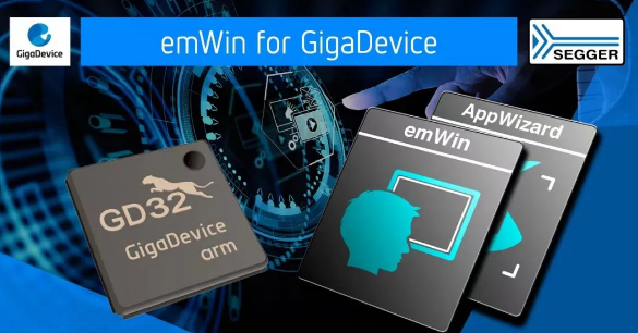
  GigaDevice and SEGGER announce their collaboration to provide customers with SEGGER emWin embedded system graphics library, free of charge. GigaDevice customers can now use emWin , as well as AppWizard, across all GD32 Cortex®-M series MCUs.  With GD32, the largest Arm®-based MCU product family in China, GigaDevice was first to launch MCUs containing Cortex®-M3, -M4, -M23, -M33, and -M7 cores. With this, GigaDevice achieves comprehensive coverage of mainstream microcontroller applications, from low energy to ultra-high performance, covering consumer to automotive grade whilst adopting the latest architectures, keeping costs low, and offering rapid real-time response. The GD32 family has 46 product series and more than 600 devices, maintaining excellent compatibility throughout.  SEGGER emWin is a cutting-edge, high-performance graphical user interface solution, optimized for minimum memory consumption, both in RAM and ROM, as well as for high speed and versatility. It provides high-quality graphic functions and can be adapted to any size display, physical or virtual. It is compatible with single-task and multitask environments, with a proprietary operating system or with any commercial RTOS such as SEGGER embOS and embOS-Ultra.  SEGGER award-winning AppWizard enables the creation of highly efficient and high-quality graphical user interfaces on any embedded system without requiring in-depth knowledge of the emWin graphics library or even the C language for coding.  Providing extensive ecosystem support is a crucial aspect of GigaDevice's MCUs. Utilizing the emWin tool further enhances graphical user interface solutions offered by GD32 Cortex®-M series MCU. SEGGER emWin can help developers achieve professional embedded GUI in a short time, and also has excellent performance on resource-limited platforms. In the end, the corresponding C language program code is generated, which can greatly reduce the development difficulty and the time to market. Drawing on decades of expertise in embedded technology and a comprehensive suite of tools for embedded systems, SEGGER continues to enhance the user experience for GD32 customers by offering greater convenience and efficiency. Furthermore, SEGGER will strengthen the collaboration with GigaDevice to jointly assist customers in accelerating their product launches.  Visit GD32 website or SEGGER Website (Partner page for GigaDevice) for a free commercial GDemWin GUI library that enables professional embedded GUI development based on the GD32 Cortex®-M series MCU hardware platform.  About GigaDevice  GigaDevice Semiconductor Inc. (SSE Stock Code 603986) is a global leading fabless supplier. The company was founded in April 2005 and headquartered in Beijing, China, with branch offices in many countries and regions worldwide, providing local support at customers' fingertips. Committed to building a complete ecosystem with four major product lines – Flash memory, MCU, sensor and analog – as the core driving force, GigaDevice can provide a wide range of solutions and services in the fields of industrial, automotive, computing, consumer electronics, IoT, mobile, networking and communications. GigaDevice has received the ISO26262:2018 automotive functional safety ASIL D certification, as well as ISO9001, ISO14001, ISO45001, and Duns certifications. In a constant quest to expand our technology offering to customers, GigaDevice has also formed strategic alliances with leading foundries, assembly, and test plants to streamline supply chain management.
Key word:
Release time:2024-03-15 15:10 reading:1829 Continue reading>>
Quicker, More Advanced <span style='color:red'>GUI</span> as TARA Systems' Embedded Wizard Partners with GigaDevice
  Created by TARA Systems GmbH, Embedded Wizard is the market-leader for embedded GUI technology. The company has announced a new partnership with GigaDevice Semiconductor, a leading supplier of high-performance memory and microcontrollers.  The partnership represents a groundbreaking update to Embedded Wizard's popular graphical user interfaces, making embedded GUI software development faster and more cost-effective for customers.  According to Mr. Eric Jin, Product Marketing Director at GigaDevice, "This collaboration is set to bring advanced solutions to our clients, providing customers with exceptional user experiences and faster time-to-market for their products."  Manuel Melic, Product Manager at Embedded Wizard and Managing Director of TARA Systems, says: "We are excited to work with GigaDevice and provide software engineers with a more comprehensive, quicker method for developing custom GUIs."  The exciting combination of leading microcontroller hardware plus powerful embedded GUI software means customers can effectively reduce the system resource footprint of advanced graphic displays and simplify the human-machine interface (HMI) development process.  Customers can be confident that the hardware will work flawlessly with all Embedded Wizard software. From idea to production, with the expertise of Embedded Wizard and GigaDevice, customers can get their GUI products to market and deploy them in less time, manage their budgets more easily.  The advantages of the partnership are easily demonstrated in the recent integration of GigaDevice's GD32 family of microcontrollers to the range of Embedded Wizard’s platform partners. Through this collaboration, customers will be treated to faster performance, lower power consumption, a richer set of peripherals and a more user-friendly graphical interface.  For a free trial of Embedded Wizard GUI software, download now at embedded-wizard.de/download.  About GigaDevice  GigaDevice Semiconductor Inc. (SSE Stock Code 603986) is a leading global fabless supplier. The company was founded in April 2005 with branch offices in many countries and regions worldwide, providing local support at customers' fingertips. Committed to building a complete ecosystem with major product lines – Flash memory, MCU, sensor, and power as the core driving force, GigaDevice can provide a wide range of solutions and services in the fields of industrial, automotive, computing, consumer electronics, IoT, mobile, networking, and communications. GigaDevice management system has achieved ISO 9001:2015 and ISO 14001:2015 certifications. Constantly looking to expand the technology offering to customers, GigaDevice has also formed multiple strategic alliances with leading foundries, assembly, and test plants to streamline supply chain management.  About TARA Systems' Embedded Wizard  Embedded Wizard is a market-leading solution for creating Graphical User Interfaces (GUIs) for embedded systems with more than 30 years of experience in the industry. Its mission is to provide developers with the most convenient and efficient tool for programming embedded GUIs by simplifying development efforts. Developers use this versatile tool to create complex user interfaces in the shortest possible time and stand out from their competitors due to the numerous highly sophisticated features of the tool. Additionally, Embedded Wizard's GUI Services team offers their customers a portfolio of different services. These range from Embedded Wizard trainings, via GUI prototyping and implementation of dedicated GUI controls up to holistic GUI application development. Under the patronage of the independent software company TARA Systems, Embedded Wizard is constantly improving and entering more industries and markets worldwide. Embedded Wizard is driven by the idea of providing a comfortable workflow for embedded systems in consumer electronics, industrial, automotive, medical, home appliances and mobile devices. GUIs created with Embedded Wizard are already used on over 100 million devices worldwide.
Key word:
Release time:2023-08-29 11:18 reading:3451 Continue reading>>
How to distinguish the role of color ring inductor in circuit from color ring resistance
  Color code inductance is also called color ring inductance. When the color ring inductor uses the current through the circuit, only fixed magnetic force lines are displayed around the inductor.         In order to improve your understanding of color ring inductor, the following is related content of color ring inductor sorted out by AMEYA360 electronic components purchasing network, hoping to provide you with reference and help. However, when the color ring inductor passes an alternating current through the coil, the magnetic force line around the color ring inductor changes with time.  First, the role of color ring inductance in the circuit  1, screen signals, color code inductance can play a role of frequency selection, when the color code inductance and electrolytic capacitor in parallel can be composed of tuning circuit. The inductance and capacitive reactance of the color code inductor in the circuit are opposite, so that the natural oscillation frequency f0 in the circuit is equal to the frequency f of the non-AC signal, so as to play a role of signal screening.  2, inhibit electromagnetic wave interference, that is, inhibit EMC interference. Color code inductor and capacitor are combined to form LC filter circuit, in which EMC interference can be suppressed.  3, stable current, color ring inductance plays a role in the circuit to stabilize the current. When the current increases, the color ring inductor generates induced electromotive force to prevent the current from increasing. When the current decreases, the color ring inductor will release the energy previously stored, thus reducing the current reduction.
Release time:2023-03-10 11:41 reading:1703 Continue reading>>
Ameya360:The A-to-Z Guide on Using Stiffener for Flex and Rigid-flex PCBs
  Lighter electronics with shrinking packages are a reality today mainly due to the emergence of flexible printed circuits (FPC). They are built on materials that can bend smoothly and improve the product’s resistance to vibration and motion. FPCs reduce interconnection defects by minimizing the connection points on the PCB. Their ability to fit in unusual shapes has largely accelerated the miniaturized designs.  With all these advantages, the demand for flex and rigid-flex PCBs has amplified in almost all electronics business sectors. But the material agility makes the flex PCBs susceptible to quick breakdown. A supporting mechanism like a stiffener is hence recommended during the assembly of flex and rigid-flex PCBs to improve the board strength and rigidity.  What stiffeners and why they are needed in flex and figid-flex PCBs  PCB stiffeners are the mechanical parts used during the assembly process to improve the strength of Flex PCBs. They enhance the durability of the PCB by reinforcing the areas in which components will be mounted. Stiffeners add thickness to the board with an impact on cost and manufacturing time in PCB production. Even Rigid-flex PCBs are benefitted from extra strengthening by adding such stiffeners.  They are more often required when the components are in the dynamic areas of the Flex PCBs. Stiffeners are used to avoid stress on the flex boards due to heavy components. There can be pressure on the pads if the connectors require frequent plug-in/plug-out. Stiffeners can hold the PCB surface flat and strong to mount SMT parts efficiently in SMT assembly. They provide the mechanical strength to sustain vibration and shock in harsh operating environments.  Stiffeners facilitate better handling of thin and flexible boards. If there is a requirement for Zero insertion force (ZIF) connectors in the design, they can support the same. Stiffeners improve the bend radius of the PCB and also reduce the stress at flex and rigid circuit junctions. So, they are an integral part of flex and rigid-flex PCBs.  Choose the PCB stiffeners with the right material  Based on the functionality different materials are used to make stiffeners. A PCB busbar is a board stiffener that can conduct electricity. It is made using conductive metals like copper, stainless steel, or aluminum. Non-metal stiffeners are made using polyimide or FR4 material.  FR4 is the common type used for PCB stiffeners in Flex PCB applications. The main purpose of using an FR4 stiffener is to provide the required support for the PCB during the assembly processes like pick-n-place of components and in reflow ovens. They also strengthen the board in areas where connectors and other through-hole parts are mounted. The usual thickness of FR4 stiffeners varies from 0.2mm to 1.5mm. They are more affordable in price compared to other types of stiffeners.  Metal stiffeners like stainless steel or aluminum are highly recommended in applications requiring rigid-flex PCBs to operate in varied temperature ranges. They are a perfect choice in applications demanding corrosion-resistant FPCs. But they are expensive and have a longer bonding process compared to other stiffener materials. Yet, aluminum is ideal for applications involving high thermal dissipation, and stainless-steel stiffeners offer enough support within smaller spaces. While stainless steel stiffeners are available in the thickness range of 0.1mm to 1.5mm, aluminum stiffeners’ thickness can be between 0.2mm to 1.5mm.  Polyimide stiffeners are made from high-temperature polymer sheets in thicknesses ranging from 0.05mm to 0.25mm. They provide exceptional solder resistance and added bond strength. Polyimide stiffeners limit the PCB bending in specific areas while preparing the boards for final assembly. They are best suited to increase the ZIF connector thickness with additional support to contact fingers on the circuit board.  How to mount the stiffeners on flex PCBs  While assembling the stiffeners on a PCB, there are a few key factors to consider. In boards using through-hole parts, it is recommended to position the stiffener on the same side as the components to provide easy access to the solder pads on the PCB. To relieve the stress, there should be around 0.762 mm of overlap of the stiffener on the exposed coverlay of the flex PCBs. If multiple stiffeners are used, then the same stiffener thickness has to be maintained.  To ensure proper alignment, FR4 stiffener holes are enlarged by around 0.3mm as compared to flex board holes. FR4 stiffeners are mounted on the array border to ruggedize the assembly array. This can assist in the automated assembly of flex PCBs similar to rigid PCBs. Also, the need for further tooling plates can be eliminated.  Stiffeners are mounted on the flex PCBs using either pressure-sensitive adhesives or thermally bonded adhesives. Pressure-sensitive adhesives are used in IPC class 2 products while thermally bonded adhesives are preferred in application-critical IPC class 3 products. Thermal bonding adhesives provide strong bonding of stiffeners to the PCB and are expensive. They damage the board significantly if the stiffeners have to be removed. Hence, the application process is quite crucial. On the contrary, pressure-sensitive adhesives are low-cost with medium bond strength. The PCB damages can be avoided with the careful removal of bonded stiffeners while using pressure-sensitive adhesives.  Can stiffeners improve PCB performance?  Using stiffeners in Flex and Rigid-flex PCBs offers several advantages in the overall performance of the product. They provide structural support in fragile areas of flex PCBs and minimize mechanical deformities like bending and warping. Also, they avoid any possible electrical shorts in the stacked PCBs of a chassis.  In harsh environments, stiffeners protect PCBs against pressure and vibration. They can also avoid mounting screws or rivets on PCBs, reducing the cost of such additional fittings. Using busbars can improve the power distribution for the ground circuit of the PCB. They can assist in quick thermal dissipation in high-temperature applications. Thus, stiffeners are remarkable in improving the overall performance and structural integrity of the FPCs.  Conclusion  To control the cost and quality of flexible printed circuits, it is important to work with an experienced contract manufacturer (CM). Building stiffener PCBs with optimized quality and reduced cost is possible if your CM has adopted quality management guidelines and is equipped with the latest technologies in the production line. Further, this comprehensive guide on stiffeners will enable you in understanding the right choice of material, adhesive types, key mounting considerations, and their usage in Flex and Rigid-flex PCBs.
Key word:
Release time:2023-02-16 15:28 reading:1906 Continue reading>>
Samsung guidance shocks: fourth-quarter profit 18 percent less than market expected
Jung Yeon-je | AFP | Getty ImagesSamsung Electronics said on Tuesday that its fourth-quarter earnings likely decreased sharply due to lackluster demand in its memory chip business as well growing competition in the smartphone segment.The South Korean tech giant predicted operating profit for the three months ended December was approximately 10.8 trillion Korean won ($9.67 billion) — a 38.5 percent drop from the previous quarter and below the 13.2 trillion won that analysts predicted.Consolidated sales for the fourth-quarter is predicted to be around 59 trillion won, lower than the 62.8 trillion won analysts predicted in a Reuters poll, and nearly 10 percent down from the third quarter.The chipmaker said weaker-than-expected demand in the memory business led to a decline in shipments and a notable drop in memory chip prices.For its smartphone business, marketing expenses in an essentially stagnant smartphone market led to decline in profitability. Over the third quarter of 2018, Samsung saw more than 13 percent year-over-year decline in global smartphone shipments, according to International Data Corporation.Samsung will disclose detailed earnings later in the month but added that difficult business conditions for the memory business would likely keep its earnings subdued for the first quarter of 2019.The weak guidance from Samsung comes after Apple lowered its revenue and gross margin predictions last week, citing a weakening Chinese economy and lower-than-expected iPhone revenue in Greater China as some of the factors.Concerns over a slowdown in the Chinese economy have kept investors on edge. It could pose a worry for Samsung since it sells memory chips used in smartphones and data centers to Chinese firms. At the same time, it also has production plants in the world's second-largest economy for some of the memory chips — those are likely to be hurt by the ongoing trade tensions between Beijing and Washington.In December, a report from the Korea International Trade Association said the trade war may pose higher risks to both Samsung and its chipmaking rival SK Hynix.At the same time, a slowdown in Chinese consumer demand could potentially affect Samsung's consumer electronics business, including smartphones. One analyst said that China accounts for between 20 to 30 percent of global consumer tech demand.
Key word:
Release time:2019-01-08 00:00 reading:3586 Continue reading>>
Apple slashes revenue guidance, says iPhone sales are weak in China
Apple lowered its Q1 guidance in a letter to investors from CEO Tim Cook Wednesday.Apple stock was halted in after-hours trading just prior to the announcement, and shares were down about 7 percent when trading resumed 20 minutes later.Apple lowered revenue guidance to $84 billion, down from the $89 to $93 billion it had previously projected. The company lowered gross margin to about 38 percent from between 38 percent and 38.5 percent.Apple blamed a variety of factors for the lowered guidance, including a weakening economy in China and lower-than-expected iPhone revenue. Apple said the lower-than-anticipated revenue happened "primarily in Greater China," but also said that upgrades to new iPhone models in other countries were "not as strong as we thought they would be."Cook's letter said fewer carrier subsidies, price increases based on the strength of the U.S. dollar and cheaper battery replacements caused the weak iPhone upgrades for the quarter."If you look at our results, our shortfall is over 100 percent from iPhone and it's primarily in greater China," Cook told CNBC's Josh Lipton in an interview Wednesday. "It's clear that the economy began to slow there for the second half and what I believe to be the case is the trade tensions between the United States and China put additional pressure on their economy."A White House spokesman did not immediately have a response to Cook's comments on the trade tensions between the U.S. and China.There have been several reports pointing to weak iPhone sales in recent months. Some Apple suppliers cut their estimates last quarter, leading many to speculate consumers weren't upgrading to the new models. Apple also took the unusual step of promoting discounted prices for iPhones on its website if customers traded in an older model. The company also increased the trade-in value of some older iPhone models.Despite the lowered guidance, Cook did point out some growth areas in the letter to investors. He said Apple's device install base increased by 100 million units over the last year. Apple has been promoting its growing install base as a way to show it can squeeze more revenue out of each of its uses through subscription services like iCloud storage and Apple Music. The company is said to be considering new subscription products through its Apple News and TV apps as well."We had sort of a collection of items going on. Some that are macroeconomic and some that are Apple specific," Cook said in his CNBC interview. "And we're not going to sit around waiting for the macro to change. I hope that it does and I'm actually optimistic, but we are going to focus really deeply on the things we can control."
Key word:
Release time:2019-01-03 00:00 reading:1317 Continue reading>>
Chipmaker Nvidia plunges after missing on revenue and guidance
Nvidia stock fell as much as 19 percent Thursday after the company reported earnings for the third quarter of its 2019 fiscal year, which ended on Oct. 28.Here's how the company did:Earnings: $1.84 per share, excluding certain items, vs. $1.71 per share as expected by analysts, according to Refinitiv.Revenue: $3.18 billion, vs. $3.24 billion as expected by analysts, according to Refinitiv.With respect to guidance, Nvidia said it's expecting $2.70 billion in revenue in the fiscal fourth quarter, plus us minus 2 percent, excluding certain items. That's below the Refinitiv consensus estimate of $3.40 billion.Overall, in the fiscal third quarter, Nvidia's revenue rose 21 percent year over year, according to its earnings statement.In its fiscal second-quarter earnings, the chipmaker fell short of analyst expectations on guidance despite beating on earnings and revenue estimates. The company's cryptocurrency mining products suffered a hefty decline in that quarter, and the trend continued in the fiscal third quarter.It has become less profitable to use graphics processing units, or GPUs, for mining, according to a recent analysis by Susquehanna. To mine cryptocurrency, computers compete to solve complex math problems in exchange for a specific amount of bitcoin or ethereum. But as both currencies have sunk in value, so too has this segment of revenue for Nvidia."Our near-term results reflect excess channel inventory post the crypto-currency boom, which will be corrected," Nvidia CEO Jensen Huang is quoted as saying in a Thursday press release. In the fiscal third quarter Nvidia's revenue from original equipment manufacturers and intellectual property totaled $148 million, which was down 23 percent year over year but above the FactSet consensus estimate of $102 million. Nvidia chocked up the decline to "the absence of cryptocurrency mining" in its earnings statement.In the quarter Nvidia had a $57 million charge related to older products because of the decrease in demand for cryptocurrency mining."Our Q4 outlook for gaming reflects very little shipment in the midrange Pascal segment to allow channel inventory to normalize," Nvidia's chief financial officer, Colette Kress, told analysts on a conference call after the company announced its results.It will take one to two quarters to go through the extra inventory, Huang said on the call."This is surely a setback, and I wish we had seen it earlier," he said.Inventory issues also affect other brands, Huang said. AMD stock fell 5 percent in extended trading on Thursday.Nvidia's gaming business segment generated $1.76 billion in revenue in the quarter, below the $1.89 billion FactSet consensus estimate.Nvidia's data center segment came in at $792 million in revenue, lower than the $821 million estimate.Revenue for the company's professional visualization business segment was $305 million, surpassing the $284 million estimate.Nvidia, like most other tech stocks, was hit hard in October, which was the worst month for the Nasdaq Composite Index since 2008. The stock is now up 4 percent since the beginning of the year.
Key word:
Release time:2018-11-16 00:00 reading:2718 Continue reading>>
STMicroelectronics acquires <span style='color:red'>GUI</span> software specialist
Release time:2018-07-11 00:00 reading:3538 Continue reading>>

Turn to

/ 2

  • Week of hot material
  • Material in short supply seckilling
model brand Quote
RB751G-40T2R ROHM Semiconductor
BD71847AMWV-E2 ROHM Semiconductor
TL431ACLPR Texas Instruments
CDZVT2R20B ROHM Semiconductor
MC33074DR2G onsemi
model brand To snap up
IPZ40N04S5L4R8ATMA1 Infineon Technologies
BU33JA2MNVX-CTL ROHM Semiconductor
BP3621 ROHM Semiconductor
STM32F429IGT6 STMicroelectronics
ESR03EZPJ151 ROHM Semiconductor
TPS63050YFFR Texas Instruments
Hot labels
ROHM
IC
Averlogic
Intel
Samsung
IoT
AI
Sensor
Chip
About us

Qr code of ameya360 official account

Identify TWO-DIMENSIONAL code, you can pay attention to

AMEYA360 mall (www.ameya360.com) was launched in 2011. Now there are more than 3,500 high-quality suppliers, including 6 million product model data, and more than 1 million component stocks for purchase. Products cover MCU+ memory + power chip +IGBT+MOS tube + op amp + RF Bluetooth + sensor + resistor capacitance inductor + connector and other fields. main business of platform covers spot sales of electronic components, BOM distribution and product supporting materials, providing one-stop purchasing and sales services for our customers.

Please enter the verification code in the image below:

verification code